
Moving picture coding apparatus

a coding apparatus and moving picture technology, applied in the direction of signal generators with optical-mechanical scanning, color television with bandwidth reduction, television systems, etc., can solve the problems of deteriorating the accuracy of the generated prediction picture, the inability to compress the image, and the available modes, so as to achieve the effect of deteriorating the prediction picture accuracy

Inactive Publication Date: 2010-07-15
KOKUSA ELECTRIC CO LTD
View PDF10 Cites 71 Cited by
  • Summary
  • Abstract
  • Description
  • Claims
  • Application Information

AI Technical Summary

Benefits of technology

[0022]In view of the above, the present invention provides a moving picture code compressing apparatus capable of compressing codes without increasing the amount of generated codes, furthermore, without deteriorating the accuracy of an image to be predicted when intra- or inter-prediction is performed in units of pixel blocks.
[0025]In accordance with the embodiment of the present invention, it is possible to provide a moving picture code compressing apparatus capable of compressing codes without increasing the amount of generated codes, furthermore, without deteriorating the accuracy of a prediction picture when intra- or inter-prediction is performed in pixel blocks.

Problems solved by technology

Further, an optical fiber currently supplied as a home broadband has a transmission rate of about 100 Mbps and thus an image cannot be transmitted without compression.
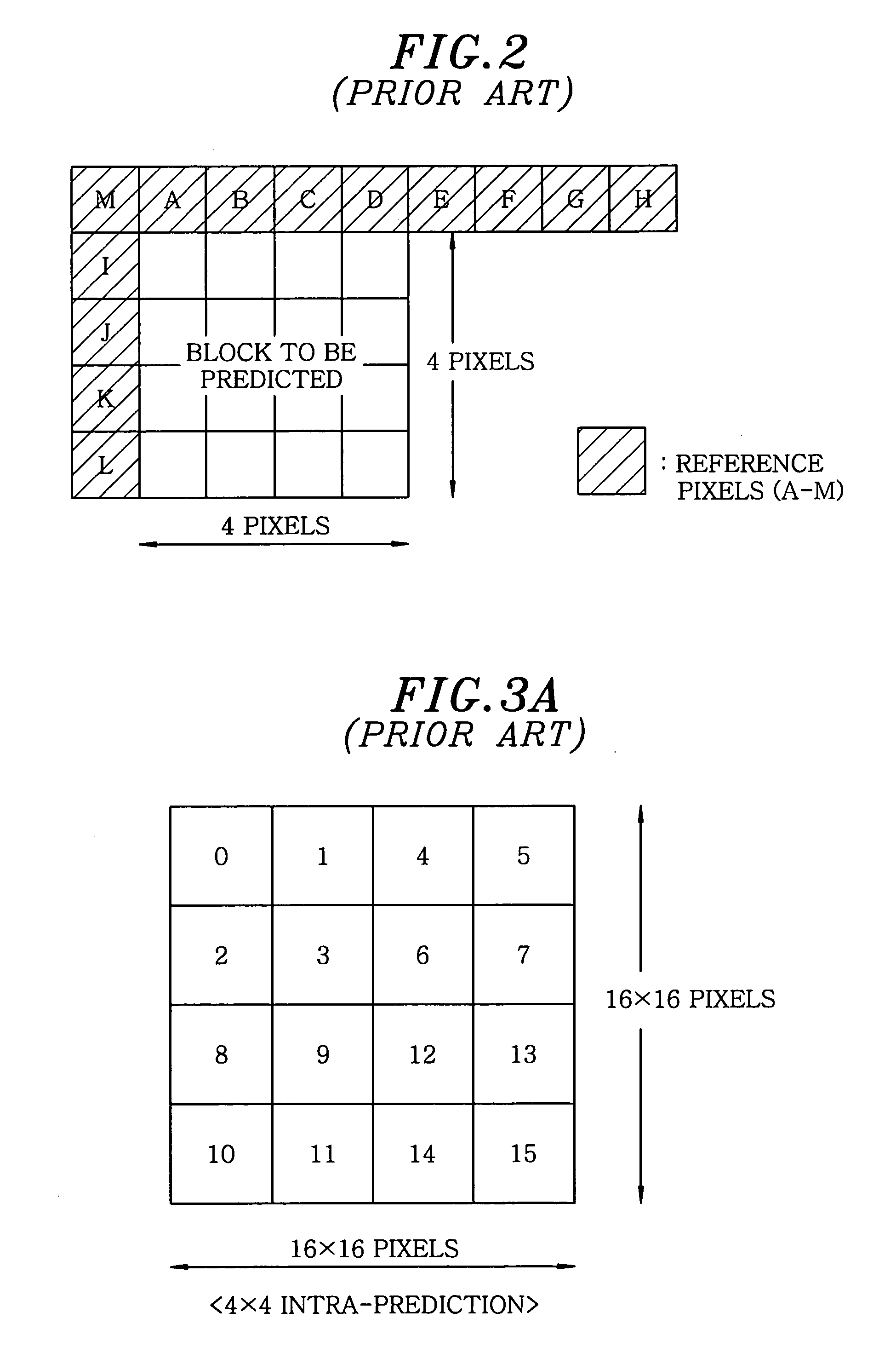
Further, since reference beyond the slice boundary is prohibited, available modes are limited.
As described above, when coding is performed based on a conventional method, limitations on available modes are generated, thereby deteriorating the accuracy of the generated prediction picture.
Further, a difference value between the prediction picture and an input picture increases due to the deterioration of the accuracy of the prediction picture.
As a result, in the coding 110 of FIG. 2, the amount of codes required for coding the blocks to be predicted, in which limitations on modes are generated, increases.

Method used


Image

  • Moving picture coding apparatus
  • Moving picture coding apparatus
  • Moving picture coding apparatus

Examples


Embodiment Construction

[0050]Hereinafter, an embodiment of the present invention will be described with reference to FIGS. 4 to 23 which form a part hereof.

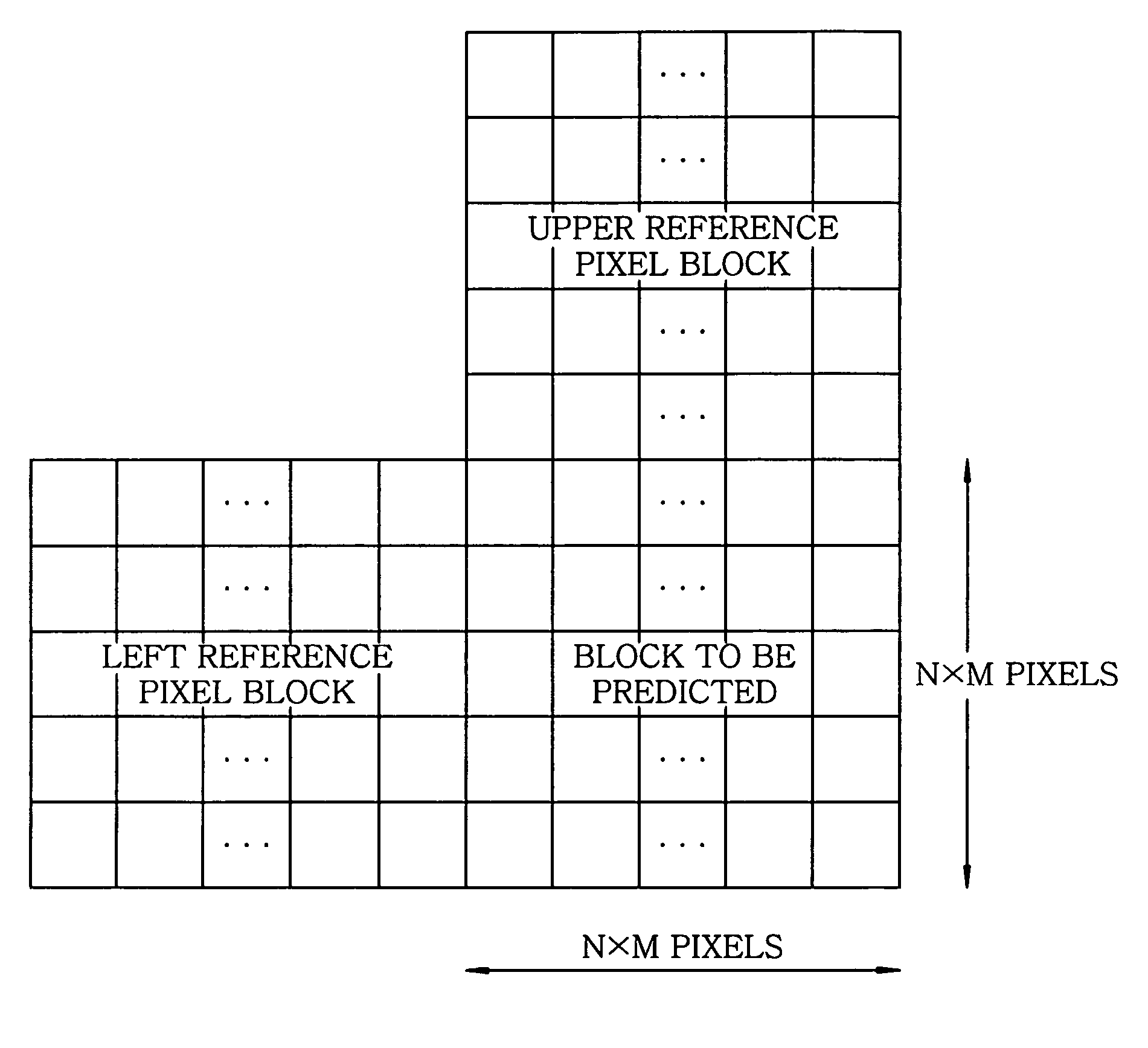
[0051]In accordance with the embodiment of the present invention, in a data compressing process performed by a moving picture coding apparatus, when image prediction is performed, data on the pixels that cannot be referred to due to the position conditions of a block to be predicted are padded so as to be used as the reference pixels of the block to be predicted.

[0052]To be more specific, in accordance with the present invention, in generating a prediction image, when upper or left reference pixels are available and pixels on the other side are not available, even if the pixels at a picture edge and at a slice end or adjacent pixels are coded by inter-prediction by performing padding based on a pixel average and a pixel difference using the available reference pixel blocks, proper reference pixels are generated regardless of limitations on the predicti...


PUM


Abstract

A moving picture coding apparatus divides a picture into basic blocks and generates a prediction image of a block to be predicted in a basic block by using adjacent pixels in reference pixel blocks adjacent to the block to be predicted as reference pixels to perform predictive coding of a moving picture. When some of the reference pixels are not available, pixel values of the reference pixels that are not available are calculated based on pixels in the reference pixel blocks. The prediction image of the block to be predicted is generated by using the calculated pixel values instead of the reference pixels that are not available.

Description

FIELD OF THE INVENTION[0001]The present invention relates to a moving picture coding apparatus; and more particularly, to a moving picture coding apparatus capable of increasing prediction accuracy when intra- or inter-prediction is performed in pixel blocks based on the standards such as MPEG-2 and H.264.BACKGROUND OF THE INVENTION[0002]Nowadays, the amount of data transmitted in the form of a moving picture is increasing day by day. For example, let's consider the amount of data of an analog television. Currently, in the case of digitizing Japanese standard television broadcasting, the number of pixels is 720 in a horizontal direction and is 480 in a vertical direction. Each pixel has a luminance component of 8 bits and two chrominance components of 8 bits. A moving picture has stage main body 30 frames per one second. Currently, since a data ratio of a chrominance component to the luminance component is 1 / 2, the amount of data for one second is 720×480×(8+8×1 / 2+8×1 / 2)×30=124,416,...

Claims


Application Information

Patent Timeline
Patent Type & Authority Applications(United States)
IPC IPC(8): H04N7/32H04N19/50H04N19/11H04N19/134H04N19/167H04N19/176H04N19/189H04N19/503H04N19/593H04N19/61H04N19/625H04N19/91
CPCH04N19/105H04N19/593H04N19/176
Inventor KADOTO, TADAKAZUKONDO, MASATOSHI
Owner KOKUSA ELECTRIC CO LTD
Learn More