Valve spring for a plate valve

Inactive Publication Date: 2010-07-22
SCHAEFFLER KG
View PDF5 Cites 7 Cited by
  • Summary
  • Abstract
  • Description
  • Claims
  • Application Information

AI Technical Summary

Benefits of technology

[0005]The object on which the present invention is based is to create a plate valve tha

Problems solved by technology

As a result, the valve element has a low restoring force combined with a short response time, i.e. the valve element opens quickly when a differential pressure

Method used


Image

  • Valve spring for a plate valve
  • Valve spring for a plate valve
  • Valve spring for a plate valve

Examples


Example

DETAILED DESCRIPTION OF THE DRAWINGS

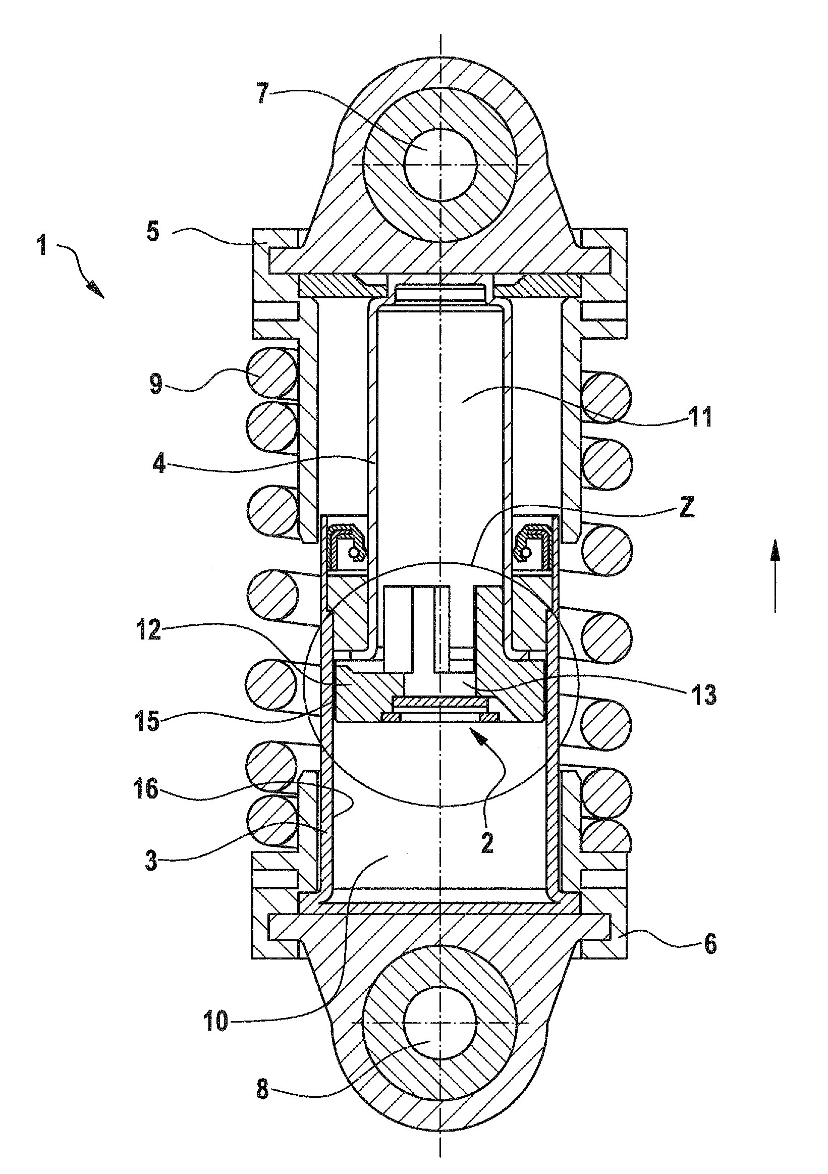
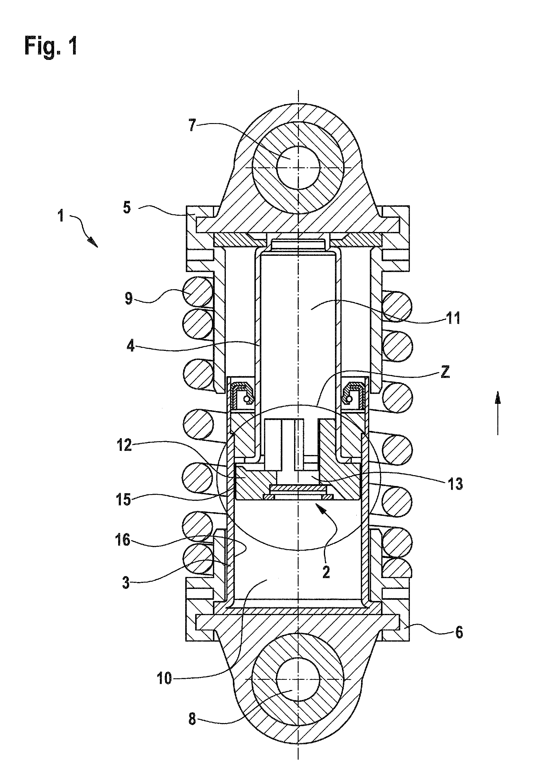
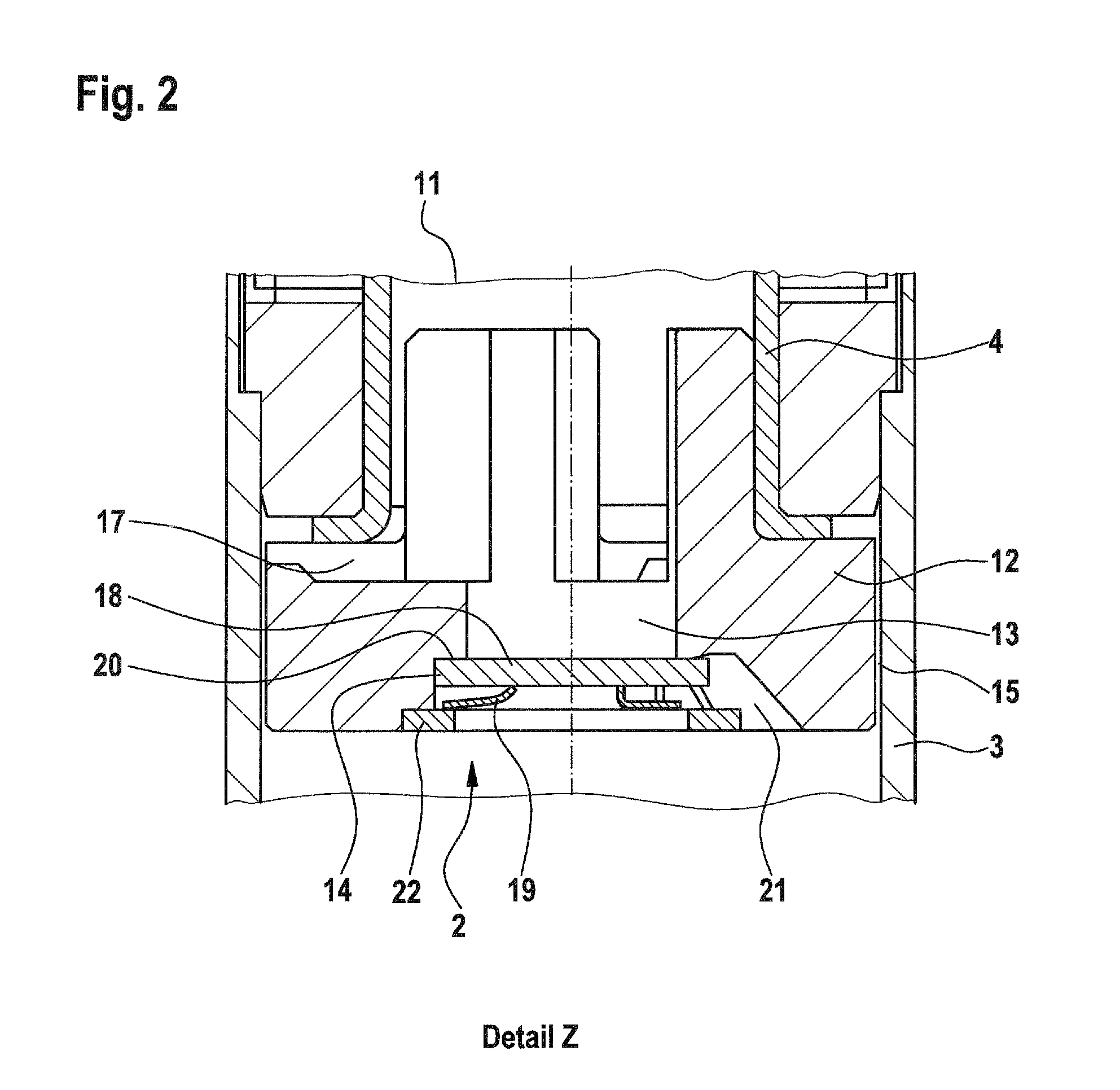
[0019]FIG. 1 shows a hydraulic tensioning element 1 for a traction mechanism drive with an integrated plate valve 2. The tensioning element 1 comprises a cylinder 3, in which a piston 4 is guided in a longitudinally displaceable manner. The cylinder 3 and the piston 4 are assigned to separate housings 5, 6, which each have a corresponding fastening lug 7, 8. A compression spring 9 around the outside of the cylinder 3 and the piston 4 produces a spreading force between these components. The piston 4 delimits a pressure space 10 enclosed in the cylinder 3 and filled with a hydraulic fluid. To allow the pressure space 10 to be supplied with the hydraulic fluid from a reservoir space 11 integrated into the piston 4, a feed bore 13 is introduced centrally in a base 12 of the piston 4. A plate valve 15 connected to the feed bore 13 is inserted as a one-way valve in a receptacle 14 in the piston base.

[0020]During an actuating movement of the piston 4 in ...


PUM


Abstract

A plate valve designed as a hydraulic one-way valve, which has a valve plate, a one-piece valve spring and a holding element. The plate valve is integrated into a piston and is assigned to a feed opening. The rotationally symmetrical plate valve is inserted into a receptacle in the piston. The valve spring, which is positioned between the valve plate and the holding element, is designed as a perforated disk, on the inside of which at least two separate spring tongues of wound design arranged offset with respect to one another are provided, the spring tongues being supported in non-positive engagement against a valve plate.

Description

FIELD OF THE INVENTION[0001]The invention relates to a plate valve designed as a hydraulic one-way valve, which comprises a valve plate, a one-piece valve spring and a holding element. The plate valve is integrated into a housing and is assigned to a control opening.BACKGROUND OF THE INVENTION[0002]EP 0 919 744 A1 discloses a disk-shaped valve member which is intended as a check valve for a tensioning device. At the upper end of the valve member there is a tappet, which is arranged in a sleeve of the filling element in the interior of the tensioning piston. The tappet is guided in the sleeve with a metal ring between them, the said ring exerting a radial force, with the result that displacing of the tappet is associated with friction. Owing to this frictional connection between the plate-shaped valve member and the tensioning piston, the opening and closure of the valve member is associated directly with the movement of the tensioning piston.[0003]U.S. Pat. No. 4,940,447 has disclos...

Claims


Application Information

Patent Timeline
IPC IPC(8): F16K1/00
CPCF16F9/3485F16H7/0836F16H7/0848F16K15/028F16H2007/0859F16H2007/0893F16K15/023F16H2007/0806
Inventor KOWALSKI, MARCO
Owner SCHAEFFLER KG
Why Eureka
Try Eureka