Distal structure of leg for musical instrument stand

Active Publication Date: 2010-07-29
YAMAHA CORP
View PDF3 Cites 4 Cited by
  • Summary
  • Abstract
  • Description
  • Claims
  • Application Information

AI Technical Summary

Benefits of technology

[0013]It is an object of the present invention to provide a simple distal structure of a leg for a musical instrument stand, allowing a player or user to easily protrude or retract a spike member from the lower end of a leg placed on the floor.
[0017]The above switch allows the spike member to protrude or retract from the ground surface upon simple depression of the operator. The present invention does not need the troublesome operation for repeatedly loosening and tightening bolts used in prior art and makes it possible to perform the protrusion / retraction operation of the spike member and the setting operation of a musical instrument in a short period of time. Since the present invention requires a single operator which can be easily recognized by the user, it is possible for the user to perform the above operations with ease, and it is possible to simplify the distal structure of a leg compared to the conventional structure using multiple buttons.
[0018]In addition, the present invention implements the “simple” switching mechanism including the presser of the operator, the projection of the rotor attached to the spike member, and the receptor aligned in the stepped interior of the storage of the case, allowing the spike member to easily protrude and retract from the ground surface upon simple depression of the “single” operator.

Problems solved by technology

This is a complicated and time-consuming operation for a player or user operating the spike member to protrude or retract from the lower end of the leg, which in turn causes a substantial load for him / her in setting the stand holding a musical instrument at a desired position.
In addition, two buttons lead to a complex structure for protruding and retracting the spike member from the lower end of the leg.

Method used


Image

  • Distal structure of leg for musical instrument stand
  • Distal structure of leg for musical instrument stand
  • Distal structure of leg for musical instrument stand

Examples


Embodiment Construction

[0036]The present invention will be described in further detail by way of examples with reference to the accompanying drawings.

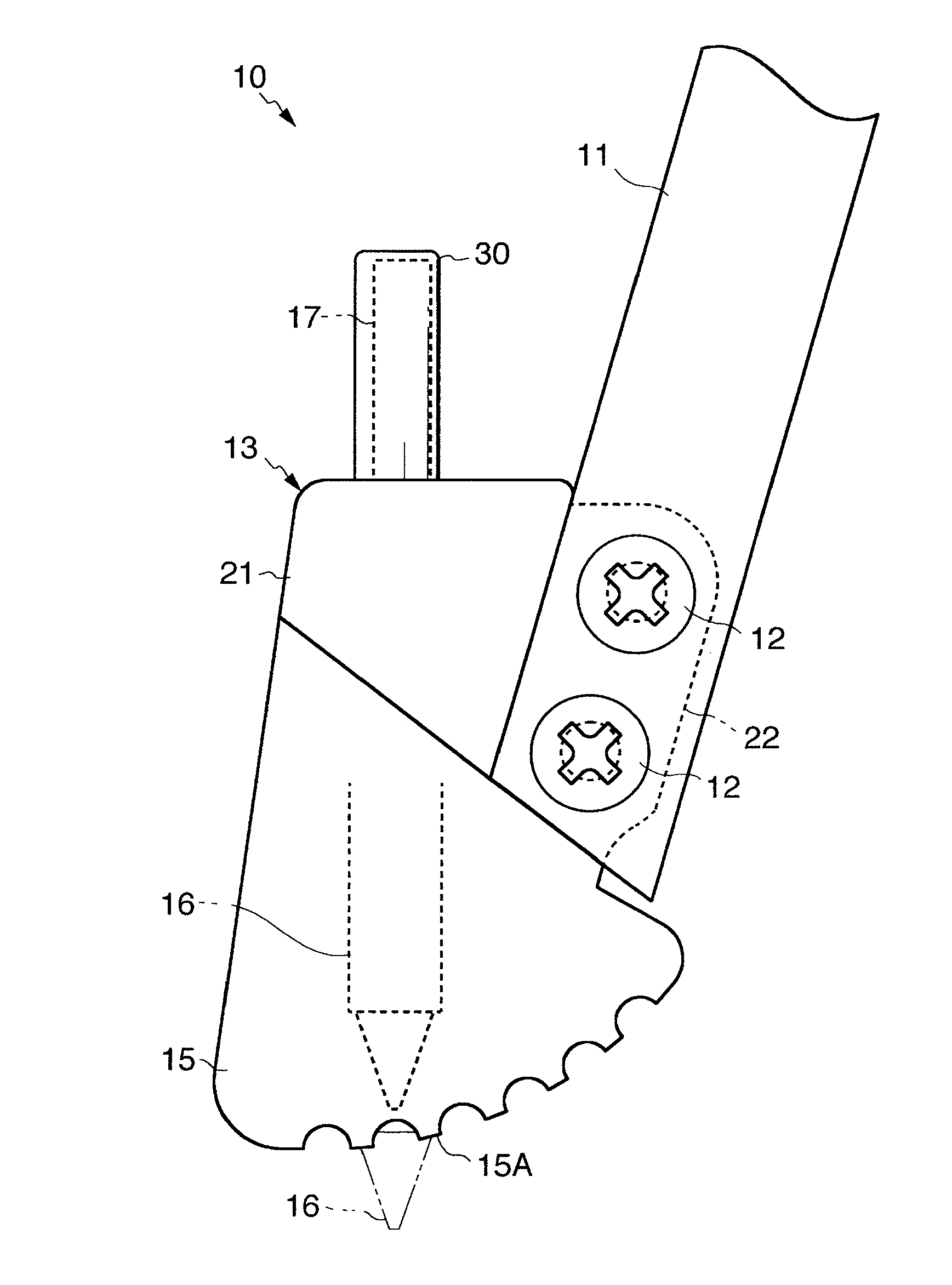
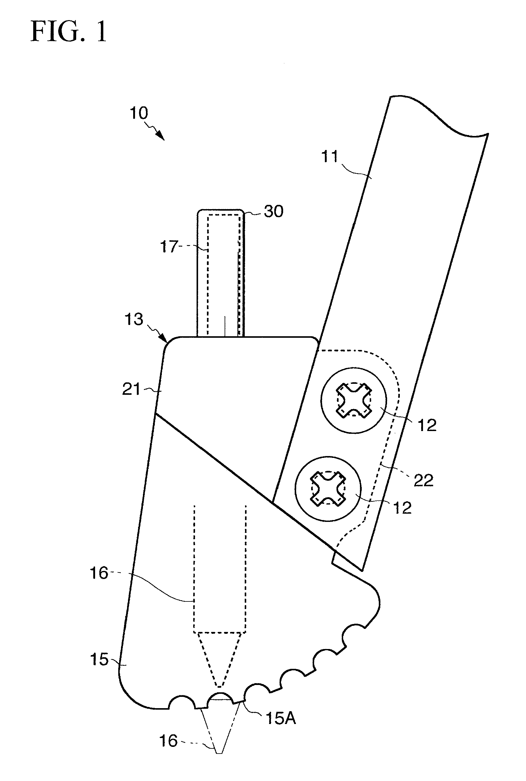
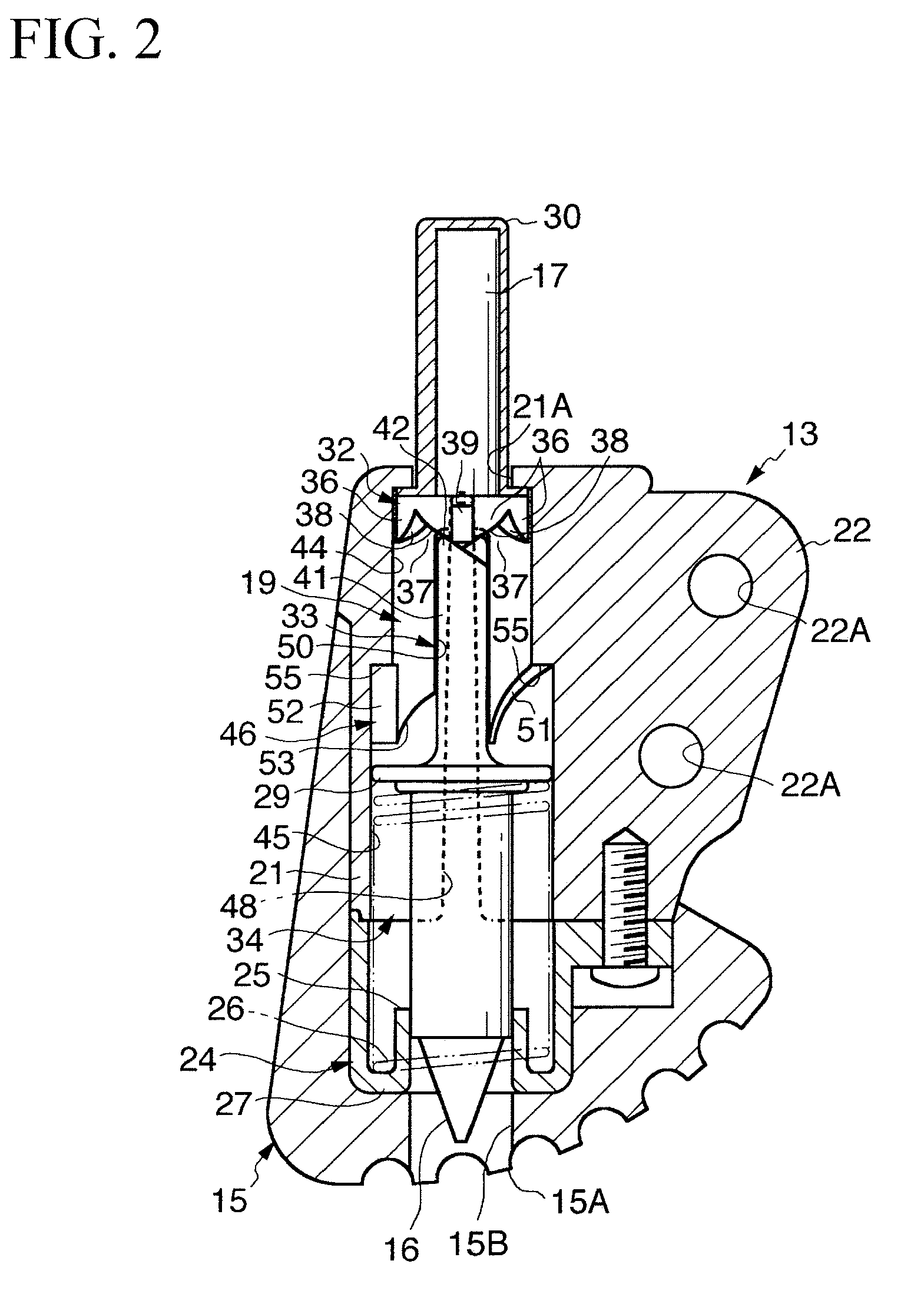
[0037]FIG. 1 is a side view showing essential parts included in a distal structure of a leg 10 according to a preferred embodiment of the present invention. FIG. 2 is a partial cross-sectional view of the distal structure of the leg 10. The leg 10 shown in FIGS. 1 and 2 is adapted to a musical instrument stand for supporting a musical instrument such as a drum and cymbal at a desired height and is interconnected to the lower end of a support rot (not shown). The leg 10 is constituted of a leg frame 11 whose base portion is interconnected to the support rod, a case 13 which is interconnected to the distal end of the leg frame 11 via screws 12, a ground portion 15 which forms the lower portion of the case 13 placed on the floor, a spike member 16 which is stored inside the case 13 and the ground portion 15, a single operator 17 which projects from the upper en...


PUM


Abstract

The distal structure of a leg for a musical instrument stand is constituted of a spike member installed inside the storage of a case having a ground portion whose ground surface is placed on the floor, a rotor interconnected to the spike member, and a single operator projected above the case. Upon a first depression, a presser of the operator depresses a projection of the rotor downward so that the spike member protrudes from the ground surface. In the protruded state of the spike member, the projection of the rotor is engaged with a receptor formed in a stepped interior of the storage. Upon a second depression, the presser of the operator depresses the projection of the rotor again so as to release the engagement between the projection and the receptor, so that the spike member moves to retract inside the storage of the case.

Description

BACKGROUND OF THE INVENTION[0001]1. Field of the Invention[0002]The present invention relates to distal structures of legs for musical instrument stands and in particular to mechanisms for protruding and retracting spike members from lower ends of legs.[0003]The present application claims priority on Japanese Patent Application No. 2009-12796, the content of which is incorporated herein by reference.[0004]2. Description of the Related Art[0005]Musical instrument stands for supporting musical instruments at desired heights, such as stands for supporting drums and cymbals, have been widely used and each constituted of a plurality of legs placed on the ground or floor, a support rod which is vertically elongated and interconnected with the legs, and a holding member which is attached to the upper end of the support rod so as to hold a musical instrument. For example, Patent Documents 1 and 2 disclose stands which are equipped with spike members at distal ends of legs for the purpose of...

Claims


Application Information

Patent Timeline
IPC IPC(8): G10D13/02G10D13/063
CPCF16M11/36G10D13/026G10D13/06G10G5/00G10D13/28G10D13/02G10D13/063
Inventor SHIGENAGA, FUMIHIRO
Owner YAMAHA CORP
Why Eureka
Try Eureka