Tire wear forecasting method and apparatus

Inactive Publication Date: 2005-04-26
BRIDGESTONE CORP
View PDF26 Cites 16 Cited by
  • Summary
  • Abstract
  • Description
  • Claims
  • Application Information

AI Technical Summary

Benefits of technology

[0011]The tread surface part temperature is high after travel since there is a high level of friction and a large amount of wear and, thus, it is possible to easily forecast the tire wear from the temperature increase in the tread surface part or from the temperature of the tread surface part. Additionally, by measuring the temperature of the entire tread surface, it is possible to estimate the wear or the tread of the tire as a whole.
[0025]When the temperature of the tire tread surface before running is different from the temperature of the road surface, for example, when the temperature of the road surface is higher than the temperature of the tire tread surface, the tire tread surface heats up by receiving heat from the road surface due to the contact between the tire tread surface and the road surface. Additionally, the heating due to the contact with the road surface will vary depending on the length of the contact surface with the road surface in the peripheral direction of the tire. Specifically, an increase in temperature when the length of the contact surface is longer (so that the duration of the contact between the road surface and the tread surface is longer) will be greater than when the length of the contact surface is shorter (so that the duration of the contact between the tread surface and the road surface is shorter).
[0026]Because of this, it is preferable to improve the forecast accuracy by correcting the increased temperature based on the length of the tire contact surface when the temperature of the tire tread surface is different from the temperature of the road surface and when tires with different contact surface lengths (when viewed in the tire peripheral direction) are used (which generally includes most tires). In particular, this is effective in increasing the forecasting accuracy when the temperature differential between the tire tread surface and the road surface is large.
[0030]The temperature measurement may be performed using a non-contact radiant thermometer, making it possible to perform the temperature measurements with ease even when the tire is rotating. One such non-contact radiant thermometer is a thermography machine.
[0031]The temperature measurement may be performed using thermography, making it possible to discern visually the temperature of the tire tread surface, or in other words, making it possible to see visually the status of wear of the tread surface.

Problems solved by technology

However, causing wear on the tires requires the travel distance to be extremely long, so there is a problem in that the testing period before test results are obtained is long.
However, an excessive amount of time must be spent in order to make the tread pattern wear image visible when measuring only a single point on the tread, so it is not possible, in practice, to estimate the wear on the tread of the tire as a whole.

Method used


Image

  • Tire wear forecasting method and apparatus
  • Tire wear forecasting method and apparatus
  • Tire wear forecasting method and apparatus

Examples


examples

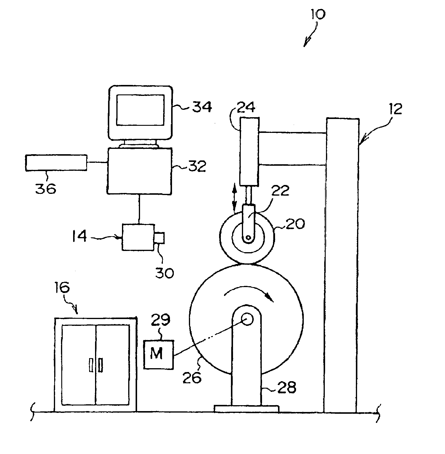
[0063]The following is an explanation of an example of the method used for forecasting the tire wear using the tire wear forecasting equipment 10 of this embodiment.

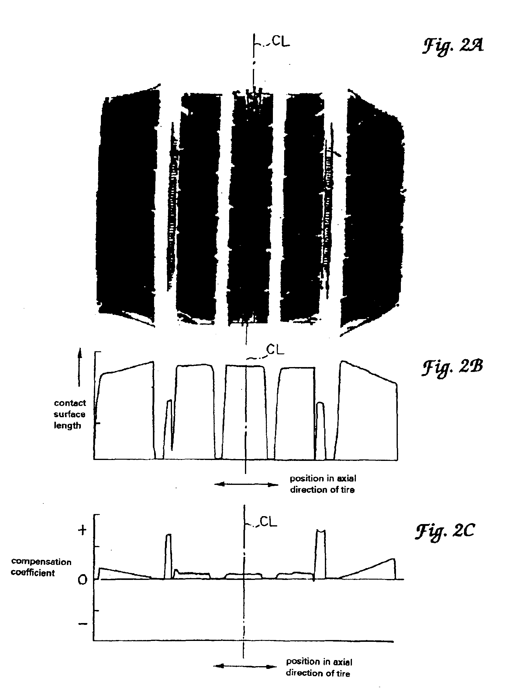
[0064](1) First, a load is applied to the tire 20 and its footprint is taken. Note that at this time the load is the same operating load as will be applied to tire 20 by the drum test equipment 12. A footprint such as shown in FIG. 2A is obtained from a tire having the tread pattern such as shown in FIG. 3.

[0065](2) The footprint is read in by the scanner 36. The computer 32 calculates the length of the contact surface in the tangential direction of the tire at the various positions in the axial direction of the tire based on the footprint that was read in, converts the contact surface lengths to compensation coefficients, and stores them in memory.

[0066]When the contact surface length at the various positions in the axial direction of the tire are displayed graphically, they appear as shown in FIG. 2B. The compensation ...


PUM


Abstract

The temperature of the tread surface part of a tire is increased by running the tire in contact with a drum. The increase in the temperature of the tread surface part is due to the heat of friction between the tread surface part and the drum. Because large increases in temperature indicate that the friction is causing a large amount of wear, it is possible to forecast with ease the amount of wear of the tire from the increase in temperature of the tread surface part. The temperature of the tread surface part can be measured using a thermography machine, and the wear in the tread can be determined by looking at an image that shows the temperature.

Description

BACKGROUND OF THE INVENTION[0001]1. Field of the Invention[0002]The present invention relates to methods and apparatus for forecasting tire wear.[0003]2. Background Art[0004]In order to investigate the relationship between tire travel distance and tire wear, conventionally, tire wear has been caused by attaching the tires to, and running the tires on, drum test equipment, or installing the tires on actual vehicles and running the tires thereon.[0005]However, causing wear on the tires requires the travel distance to be extremely long, so there is a problem in that the testing period before test results are obtained is long. More rapid methods for forecasting tire wear have therefore been proposed.[0006]In the past, when forecasting tire wear, a method has been used in which the shearing force operating on the tire tread and the movement (from the deformation) is measured.[0007]However, an excessive amount of time must be spent in order to make the tread pattern wear image visible whe...

Claims


Application Information

Patent Timeline
IPC IPC(8): G01M17/02G01B21/00B60C25/00G01J5/48
CPCG01M17/027
Inventor KURATA, TAKAYUKI
Owner BRIDGESTONE CORP
Why Eureka
Try Eureka