
Bath chair

Active Publication Date: 2015-07-23
AGATSUMA CO LTD
View PDF0 Cites 4 Cited by
  • Summary
  • Abstract
  • Description
  • Claims
  • Application Information

AI Technical Summary

Benefits of technology

[0009]As described above, the bath chair of the present invention is made such that the abutment members are individually fixed to the each both ends of the operating shaft, and the backrest is supported by the abutment member and one of the steps formed at the back side of the bearing member abutting against each other. The plurality of steps is provided so that an inclination angle of the backrest can be adjusted to positions corresponding to the each step. The lever is provided to the operating shaft and is energized to the direction in which the lever is rotated downward. Consequently, reclining operation can be performed by the lever being pulled up against the energizing force of the operating shaft so as to rotate the operating shaft, whereby abutment between the abutment member and one the steps is released. This means that the reclining operation can be performed with ease by operating the lever in one direction. In addition, the operating shaft rotates smoothly when the reclining operation is performed since a direction of force for pulling up the lever and a direction of rotation of the operating shaft coincide with each other. Further, according to a structure of the present invention, the backrest can be raised by simply raising the backrest by hand without operating the lever only in a raising direction of the backrest.
[0010]The latching projection is provided to the abutment member, and the latching hole is formed on the front side wall surface of the topmost step of the plurality of steps so as to be latched with the latching projection. In performing the reclining operation by raising up the backrest, when the abutment member reaches the topmost step, the latching projection of the abutment member is latched to the latching hole formed on a front side wall surface of the topmost step, whereby further rotation of the backrest is restricted. Unintentional forward folding of the backrest is thus prevented.
[0011]A flat portion is formed on a distal end of the abutment member. The each plurality of steps is made up of three steps, the top step, the middle step, and the bottom step. The top step and the bottom step are formed into flat surfaces, and the middle step is formed into the inclined surface which inclines downward toward rear direction. By doing this, the abutment member abuts on the step in surface to surface contact, whereby the backrest can be supported by the abutment member more stably. In addition, posture of an infant can be changed such as from seating to laying or vice versa with ease.

Problems solved by technology

The rotational force makes parallel movement of the engaging member in lateral direction difficult, although the connecting member should move parallel in lateral direction.
This interferes with transmission of a pinching force on the operating members to elastic members directly.
Consequently greater force is required for retracting the engaging rods relative to elastic force of the elastic member; hence the reclining operation cannot be performed easily with one hand.

Method used


Image

  • Bath chair
  • Bath chair
  • Bath chair

Examples


Embodiment Construction

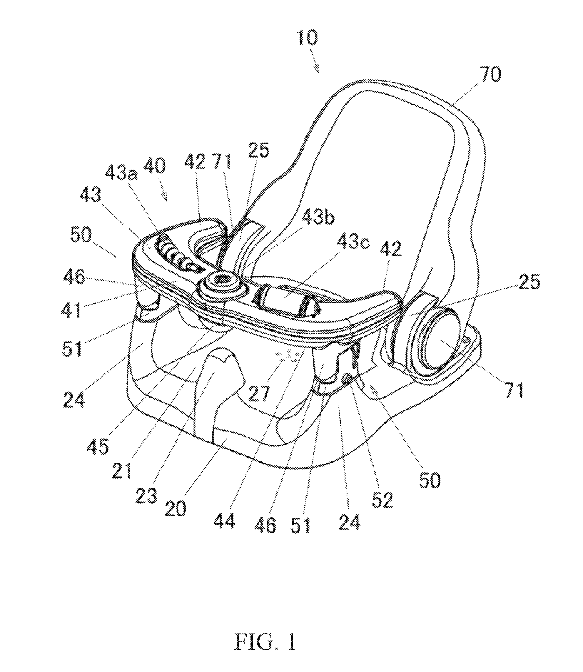
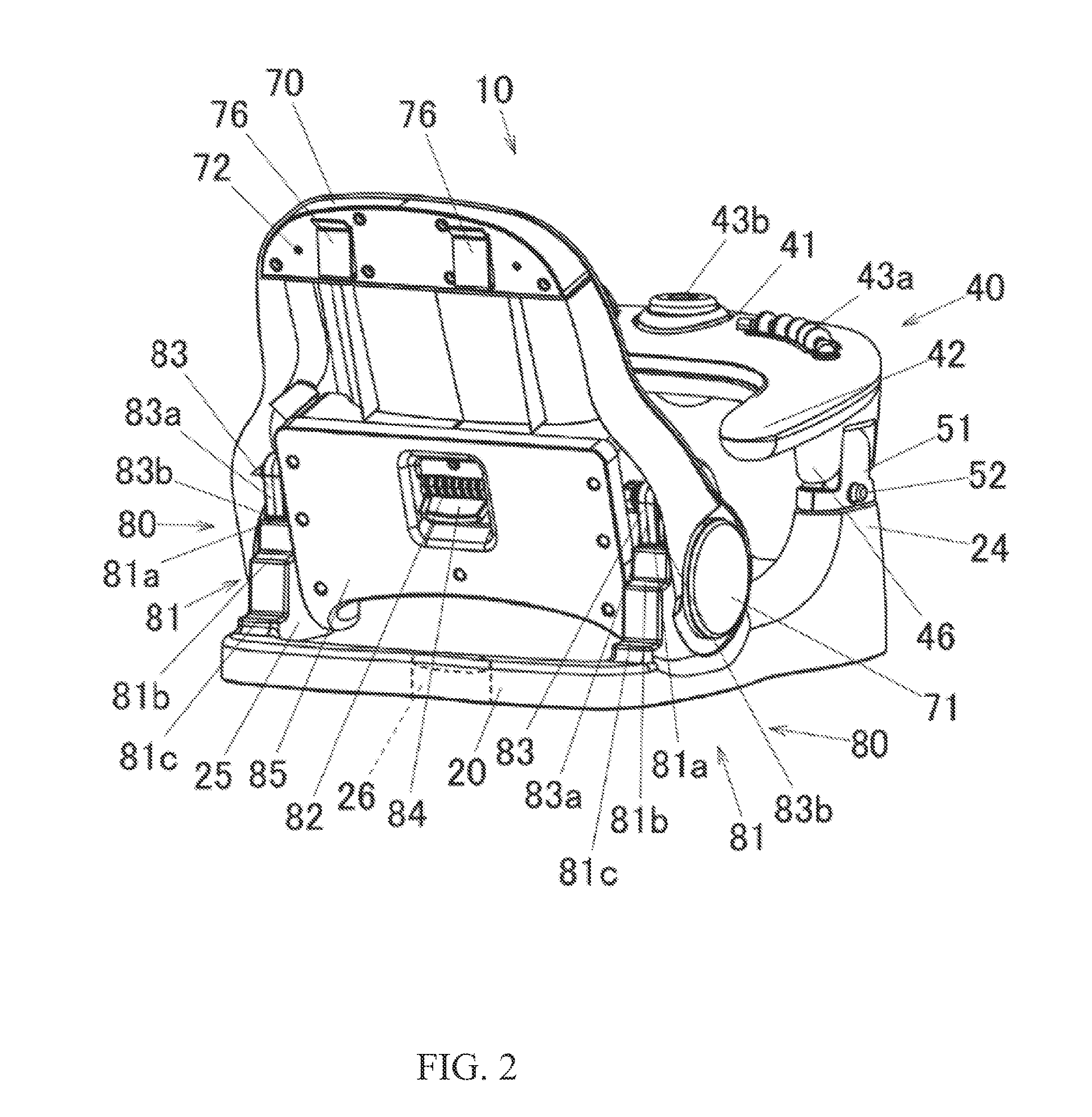
[0021]Embodiments of the present invention will be described with reference to FIGS. 1 to 9.

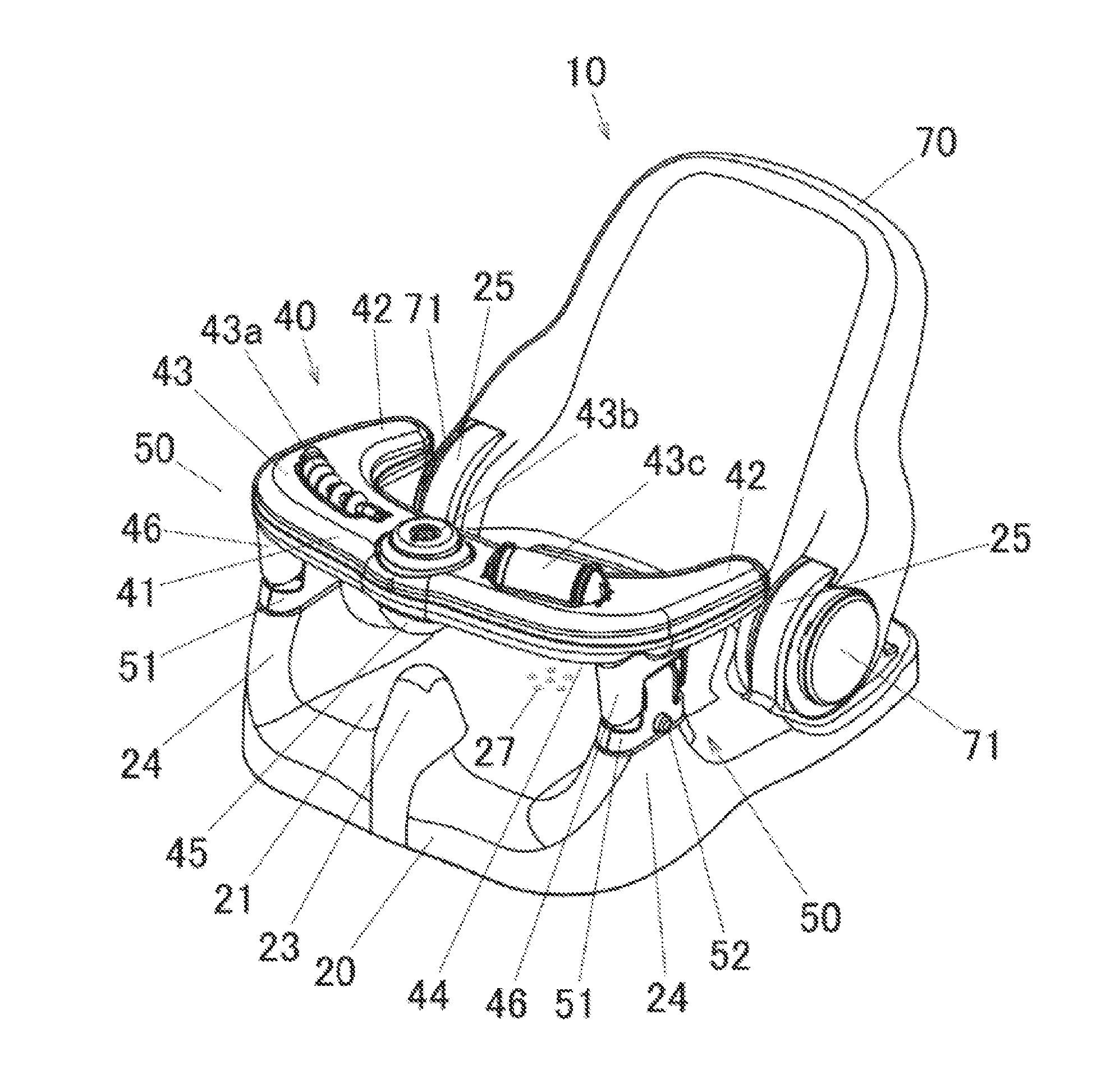
[0022]FIG. 1 is a front left perspective view of a bath chair 10, according to the present invention, having a handle for a bath chair. In descriptions hereinafter, a handle 40 side of the bath chair 10 is referred to as front, and a backrest 70 side is referred to as rear. Similarly, when viewed from a user's perspective on the bath chair 10, a left hand side is referred to as left, a right hand side is referred to as right, a seat 21 side on a base 20 of the bath chair 10 is referred to as top, and a reverse side of the top is referred to as bottom.

[0023]The bath chair 10 includes the base 20 on a top surface of which the seat 21 is formed, a backrest 70 which is connected rotatably to the base 20, and a handle 40 provided laterally in a front upper space of the base 20. A plurality of holes 27 is provided substantially in a center of the seat 21. The plurality of holes 27 prevents water fr...


PUM


Abstract

A bath chair having a reclining mechanism with enhanced operability and durability. A backrest is rotatable provided to bearing members at a rear of a base, an operating shaft is laid across a back of the backrest, a lever is provided to a center of the operating shaft. The operating shaft is biased so that the lever is pressed downward; abutment members fixed to both ends of the operating shaft and a step member having a plurality of steps provided to a rear of the bearing member abut against each other to support the backrest. When the lever is pulled up, the abutment members are rotated upward, the abutment between the step members and the abutment members are released, and then the backrest can be adjusted its inclination angle.

Description

CROSS-REFERENCE TO RELATED APPLICATION[0001]This application is based upon and claims the benefit of priority under 35 USC 119 of Japanese Patent Application No. 2014-008386 filed on Jan. 21, 2014, the entire disclosure of which, including the description, claims, drawings, and abstract, is incorporated herein by reference in its entirety.FIELD OF THE INVENTION[0002]The present invention relates to a bath chair for infants. More specifically, the present invention relates to a reclining mechanism of a backrest of a bath chair for infants.BACKGROUND OF THE INVENTION[0003]Currently, bath chairs are provided for taking care of an infant in a bathroom. These bath chairs comprise a seat having a protrusion at a front center part, a seat back having a reclining mechanism, and a handle provided from side to side above a front side of a seat. Heretofore, various proposals have been made on structures of the reclining mechanism.[0004]For example, Japanese Patent No. 5140839 describes a bath ...

Claims


Application Information

Patent Timeline
IPC IPC(8): A47K3/12A47C1/024A47D1/00
CPCA47K3/127A47C1/024A47D1/002A47K3/122A47D1/0085
Inventor TODOKORO, SHINJI
Owner AGATSUMA CO LTD
Learn More