
Mixing system control method, apparatus and program

Active Publication Date: 2006-07-18
YAMAHA CORP
View PDF6 Cites 27 Cited by
  • Summary
  • Abstract
  • Description
  • Claims
  • Application Information

AI Technical Summary

Benefits of technology

[0007]In view of the foregoing, it is an object of the present invention to provide a mixing system control method, mixing system and computer program which allow optimal scene recall operation to be performed with ease.
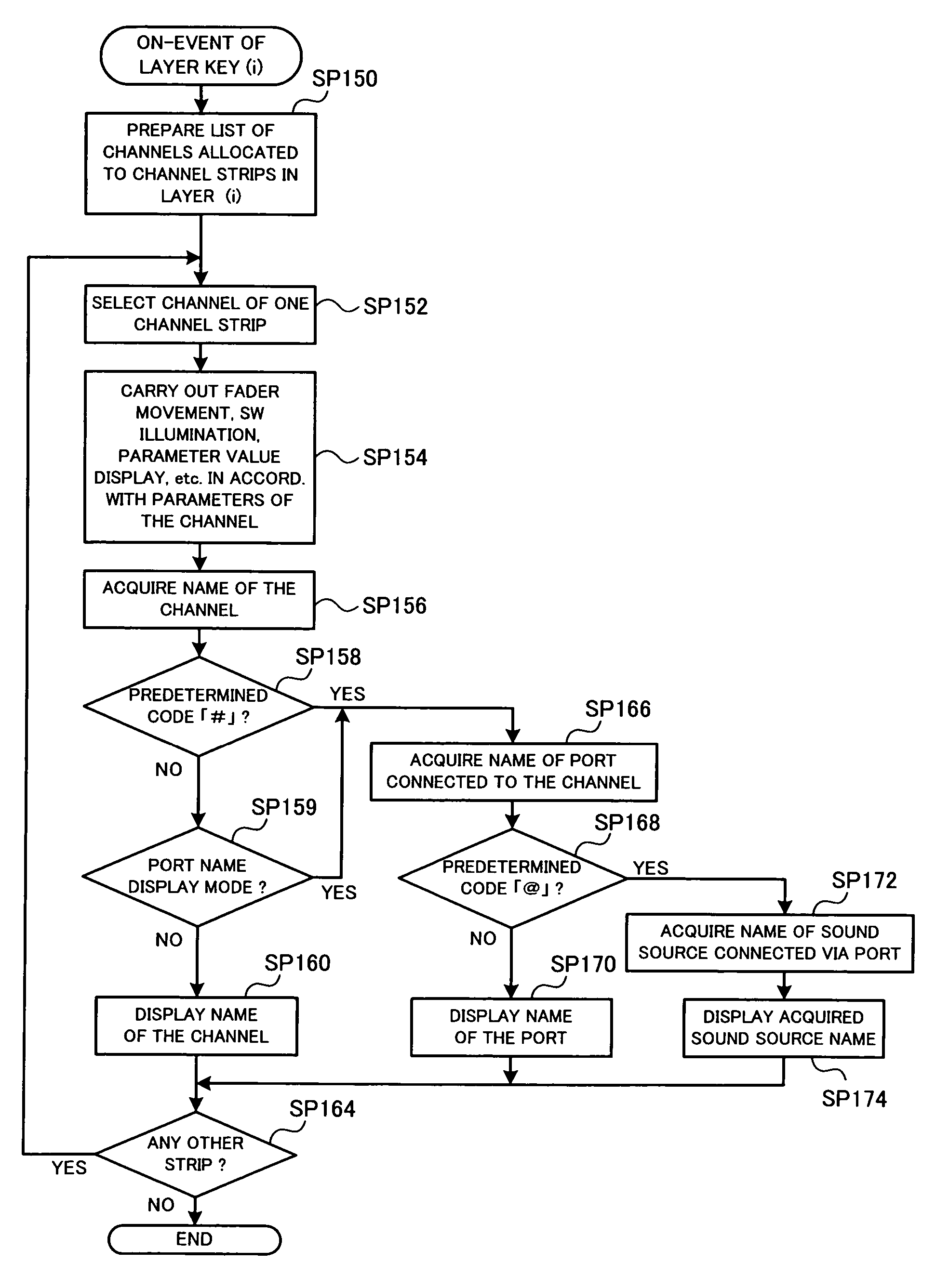
[0008]It is another object of the present invention to provide a mixing system control method, mixing system and computer program which allow optimal name display to be performed in accordance with a form of use of the mixing system.

Problems solved by technology

Therefore, according to the technique disclosed in the above-identified document “DM 2000 Instruction Manual”, there would arise a need for a human operator of the mixing system to newly set the recall safe function each time scene recall operation is performed during an actual performance, which would undesirably complicate the necessary operation.
However, the disclosed technique presents the problem that, even where any given one of the input / output channels has been assigned a particular channel name, the assigned channel name would become insubstantial or useless if the input / output port allocated to the given input / output channel is changed.

Method used


Image

  • Mixing system control method, apparatus and program
  • Mixing system control method, apparatus and program
  • Mixing system control method, apparatus and program

Examples


Embodiment Construction

1. Hardware Setup of Embodiment

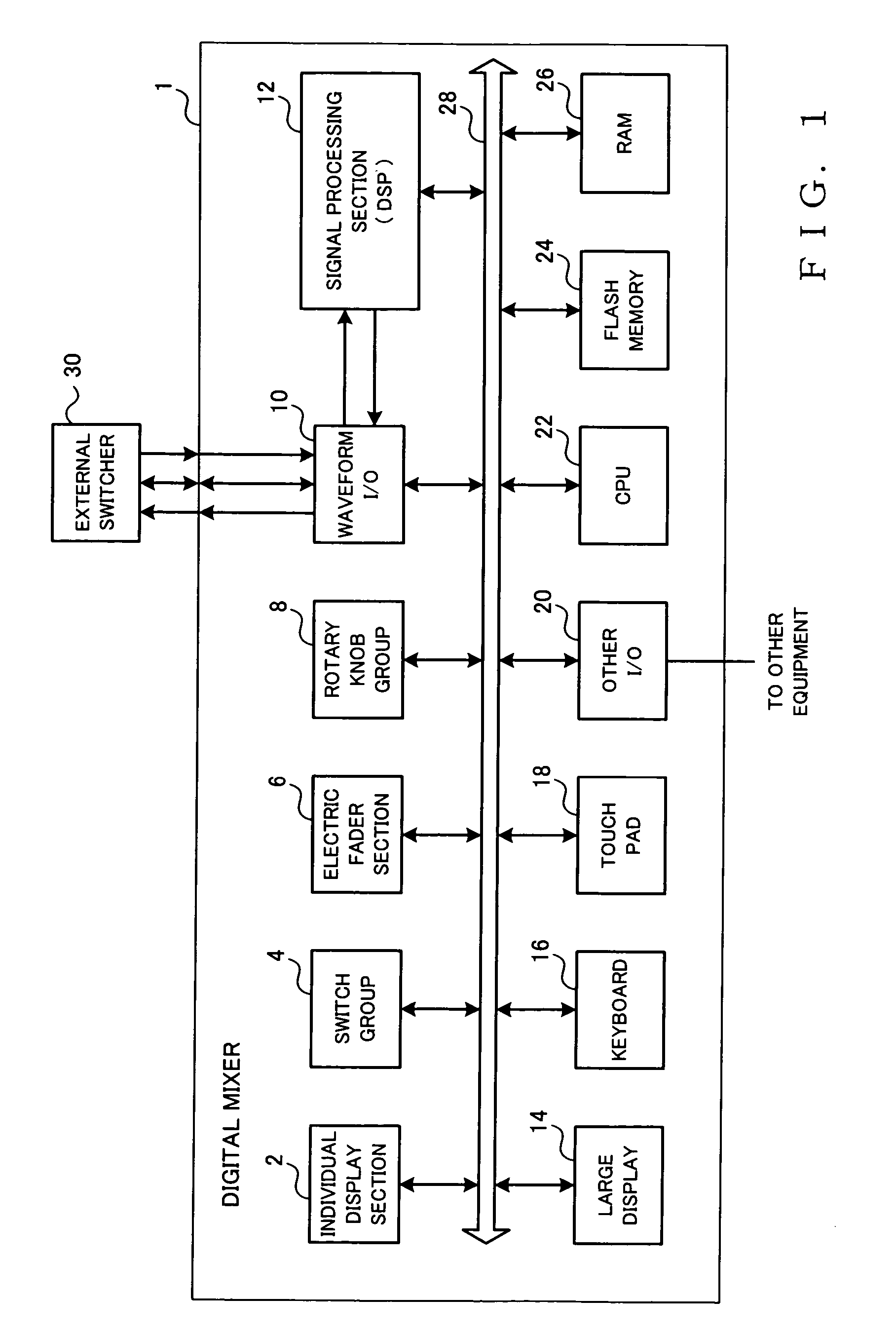
[0030]Now, a description will be made about an example general hardware setup of a mixing system 1 in accordance with an embodiment of the present invention, with reference to FIG. 1.

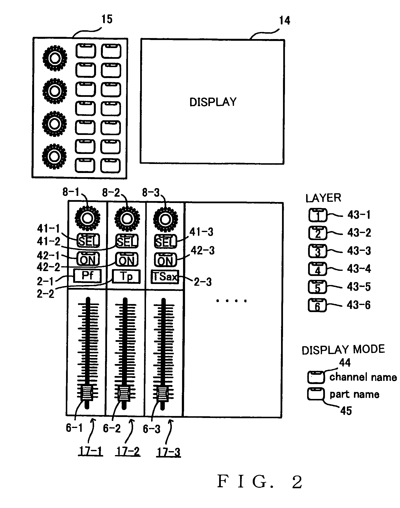
[0031]The mixing system 1 includes an electric fader section 6 for adjusting signal levels of individual input / output channels in response to operation by a human operator. The electric fader section 6, including a plurality of electric faders 6-1–6-n (see FIG. 2) is constructed so that its operating position is automatically set in accordance with an operation command given via a bus 28. The mixing system 1 also includes an individual display section 2 that includes a plurality of display elements 2-1–2-n (see FIG. 2) that correspond to the electric faders 6-1–6-n on a one-to-one basis; a string of a predetermined number of characters (e.g., alphabetical letters) is displayed on each of the individual display elements 2-1–2-n.

[0032]Further, in the mixing system 1 of FIG. ...


PUM


Abstract

In order to set in advance, for each scene, setting data that should belong to (or should not belong to) a recall range, a predetermined recall setting window is displayed for a current data set representing current settings of a mixing system. Buttons in a parameter selection section correspond to parameters of each channels belonging to the current data set, and the buttons can turned on and off. When the current data set is to be recorded as a scene data set, settings of the recall setting window are also stored as part of the current data set. When the scene is to be recalled, only setting data of parameters, having been set as data belonging to the recall range, are recalled. Also, editing of a channel name is permitted in order to perform optimal name display for channel strips of the system in accordance with a form of use of the system.

Description

BACKGROUND OF THE INVENTION[0001]The present invention relates to an improved control method, apparatus and computer program suitable for controlling mixing systems.[0002]U.S. Pat. No. 5,578,778 discloses a technique for setting parameters for an electronic musical instrument, in accordance with which any change in parameters set by a human player is inhibited in a freeze setting mode. Generally, in mixing systems, parameter values in mixing algorithms are determined in accordance with ON / OFF states and other operating states of various buttons, faders and other operators. In recent years, of the mixing systems, particularly those intended for commercial use, there have been known ones which are constructed to store parameter values in memory so as to reproduce the thus-stored values (setting data) on an operation panel through one-touch operation (e.g., with a single keystroke). For example, as optimal setting data are set for each scene on a stage during rehearsal of a concert, th...

Claims


Application Information

Patent Timeline
IPC IPC(8): G10H7/00G10H1/00G10H1/08H04H60/04
CPCG10H1/0008H04H60/04G10H1/08
Inventor AISO, MASARUTERADA, KOTARO
Owner YAMAHA CORP
Learn More