Connection structure body and rotary connector apparatus provided with connection structure body

Active Publication Date: 2019-08-29
FURUKAWA ELECTRIC CO LTD +1
View PDF6 Cites 1 Cited by
  • Summary
  • Abstract
  • Description
  • Claims
  • Application Information

AI Technical Summary

Benefits of technology

The patent text describes a connection structure body and a rotary connector device that can detect breaks with ease and high accuracy, leading to high connection reliability and safety. The break detection is achieved by configuring a circuit capable of detecting breaks in the FFCs caused by excessive rotation. The length of the FFCs in the annular space formed by the stator and the rotator is different, so the FFC with the shortest length is easily broken, followed by the remaining FFCs in order of their length. The goal is to improve safety and reliability in the connection structure.

Problems solved by technology

Thus, the FFC of the rotary connector device is installed to have a length and an extra length in accordance with a predetermined number of times of rotations such that the steering wheel can rotate clockwise or counterclockwise from a neutral position for a predetermined number of times. However, in a manufacturing process of a vehicle, in some cases, the rotary connector device is installed in a state where the steering wheel is not at the neutral position, and thus a problem may arise in which a so-called excessive rotation, in which the rotator of the rotary connector device rotates a predetermined number of times or more, occurs, and this excessive rotation causes a break of the FFC or a break of a connecting portion between the FFC and a connection tool.
This is not ideal in terms of connection reliability and safety.
In addition, when the excessive rotation occurs in the rotary connector device, the width direction end portion of the FFC is most likely to receive external force, hence, a break tends to occur in order, at a circuit arranged at the width direction end portion of the FFC and a circuit arranged at the width direction center portion of the FFC.

Method used


Image

  • Connection structure body and rotary connector apparatus provided with connection structure body
  • Connection structure body and rotary connector apparatus provided with connection structure body
  • Connection structure body and rotary connector apparatus provided with connection structure body

Examples


Embodiment Construction

[0025]Hereinafter, an embodiment of the will be described in detail with reference to drawings.

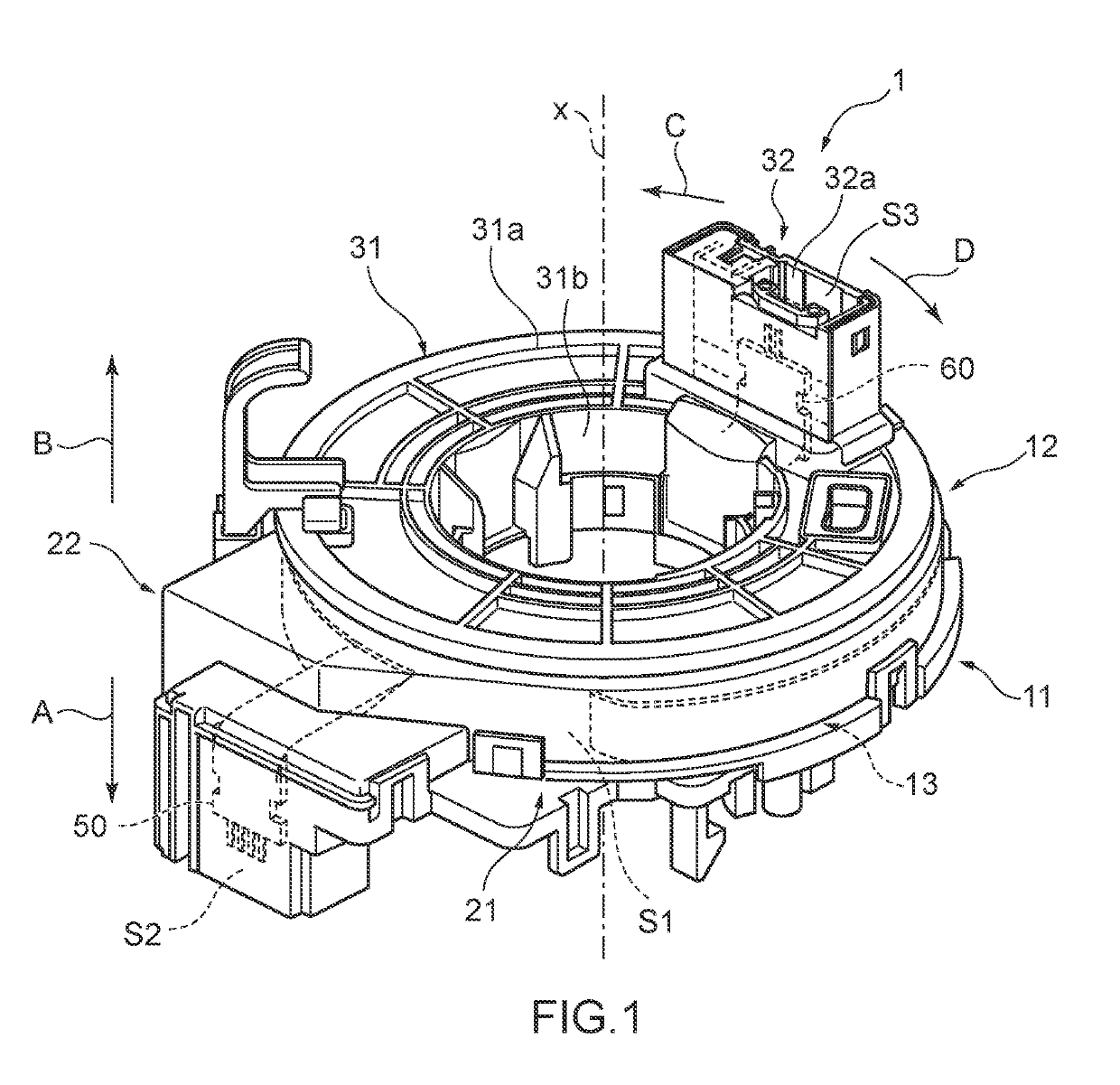
[0026]FIG. 1 is a perspective view schematically illustrating a rotary connector device according to the present embodiment. The rotary connector device of FIG. 1 is represented as one example, and the configuration of the rotary connector device according to the disclosure is not limited to one in FIG. 1.

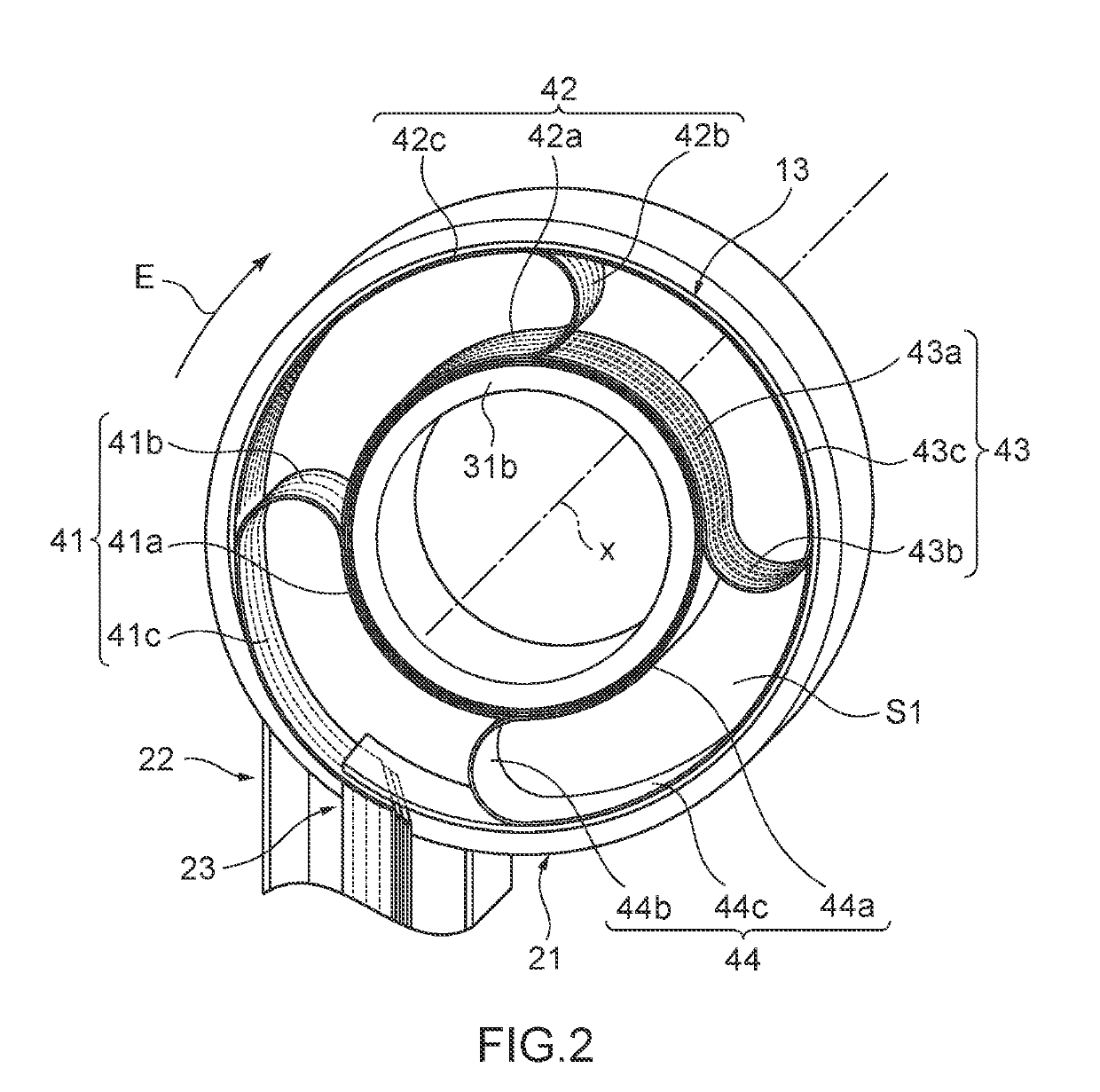
[0027]In FIG. 1, a rotary connector device 1 includes a stator 11, a rotator 12 that is rotatably attached to the stator 11, and a flexible flat cable group 13 (hereinafter referred to as “FFC group”) that is housed in windable and unwindable manners in an annular space S1 around an axis line x formed between the stator 11 and the rotator 12. In a vehicle, the stator 11 is mounted on a vehicle body of the vehicle, and the rotator 12 is attached to a steering wheel.

[0028]The stator 11 includes a stator main body 21 that includes a circular engagement hole (not illustrated) centered on the ...


PUM


Abstract

Provided is a connection structure body capable of detecting a break with ease and high accuracy and achieving high connection reliability and safety. A connection structure body 2 includes a first FFC (41), a stator side primary molding body (50), and a rotator side primary molding body (60) which are attached to both end portions (41A) and (41B) of the first FFC respectively and are able to make an electrical connection between the first FFC and the outside. The rotator side primary molding body 60 includes busbars (61-1a), (61-1b), (61-1c), and (61-1d) arranged in parallel to each other corresponding to busbars (51-1a to 51-1d), a conductive portion (61-2) that electrically connects a pair of busbars (61-1a) and (61-1d) positioned on both ends respectively in the alignment direction of the busbars (61-1a to 61-1d), and a busbar case (62) for holding the busbars (61-1a to 61-1d) in such a manner that the busbars (61-1a to 61-1d) are partly exposed. The busbars (61-1a) and (61-1d) and the conductive portion (61-2) constitute an abnormality detection circuit by forming a part of a closed circuit.

Description

CROSS REFERENCE TO RELATED APPLICATIONS[0001]This is a continuation application of International Patent Application No. PCT / JP2017 / 038837 filed Oct. 27, 2017, which claims the benefit of Japanese Patent Application No. 2016-219165, filed Nov. 9, 2016, the full contents of all of which are hereby incorporated by reference in their entirety.TECHNICAL FIELD[0002]The disclosure relates to a connection structure body and a rotary connector device provided with the connection structure body and particularly relates to a connection structure body constituting a circuit formed of a flexible flat cable, and a rotary connector device provided with the connection structure body.BACKGROUND ART[0003]In a vehicle such as a four-wheeled automobile, a rotary connector device for supplying electric power to an airbag device or the like is attached to a connecting portion between a steering wheel for steering and a steering shaft. The rotary connector device is attached to the steering shaft to surro...

Claims


Application Information

Patent Timeline
IPC IPC(8): B60R16/027B62D1/04H01R35/04H01R4/58
CPCB60R16/027H01R4/58H01R35/04B62D1/04H01R35/025H01R2201/26
Inventor UTSUNOMIYA, HIROFUMIKANAZAWA, MASASHI
Owner FURUKAWA ELECTRIC CO LTD
Why Eureka
Try Eureka