Radial shaft seal, radial shaft seal assembly and method of installation

Active Publication Date: 2010-07-29
TENNECO
View PDF37 Cites 39 Cited by
  • Summary
  • Abstract
  • Description
  • Claims
  • Application Information

AI Technical Summary

Benefits of technology

[0009]In general terms, this invention provides a radial shaft seal assembly having features that facilitate making a proper oil side installation, even in conditions of shaft-to-bore misalignment, a

Problems solved by technology

The pressure differential developed across the seal (between the oil and air side of the seal) can impart an axial load on the seal in one direction or the other (a vacuum or increased pressure in the

Method used


Image

  • Radial shaft seal, radial shaft seal assembly and method of installation
  • Radial shaft seal, radial shaft seal assembly and method of installation
  • Radial shaft seal, radial shaft seal assembly and method of installation

Examples


Example

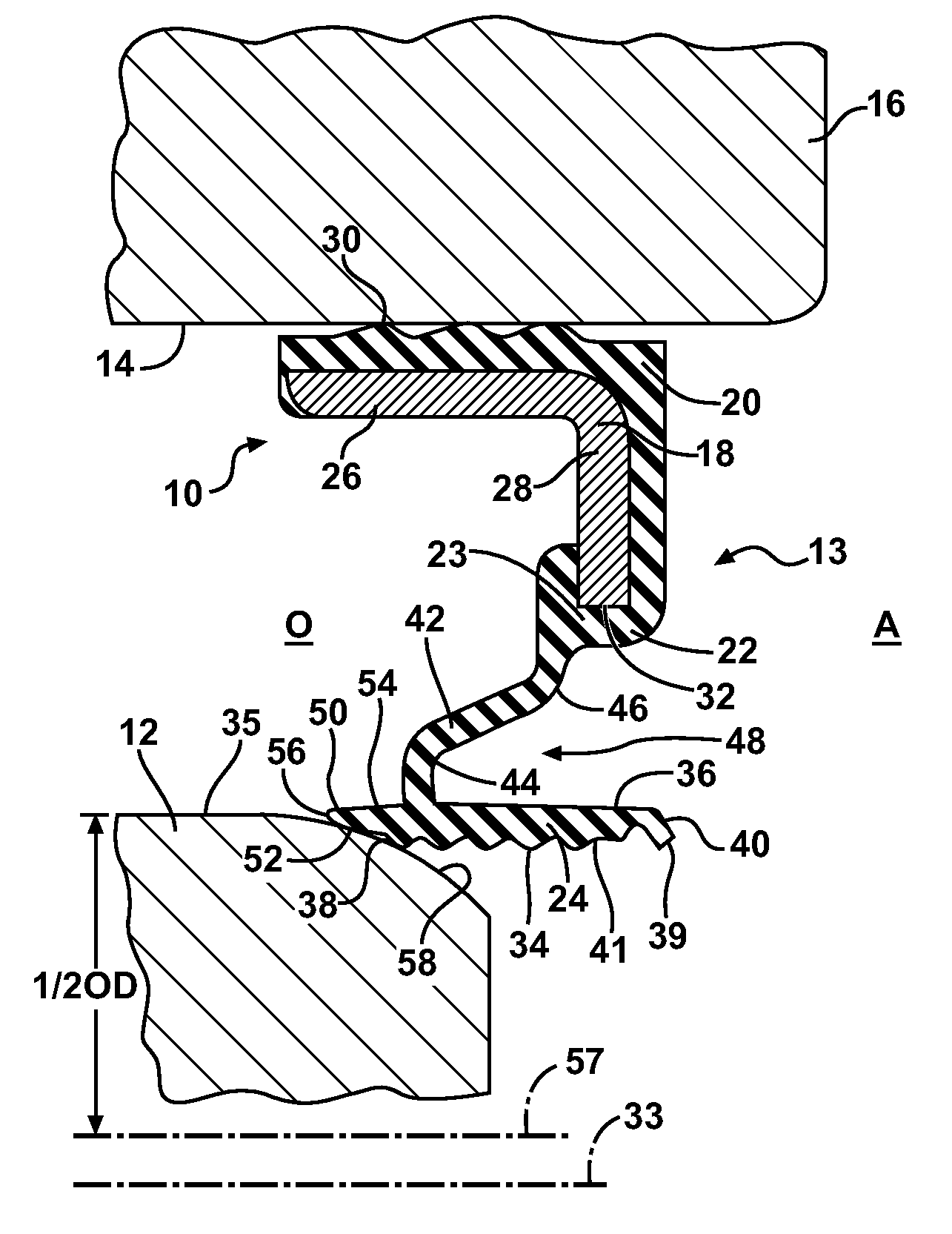
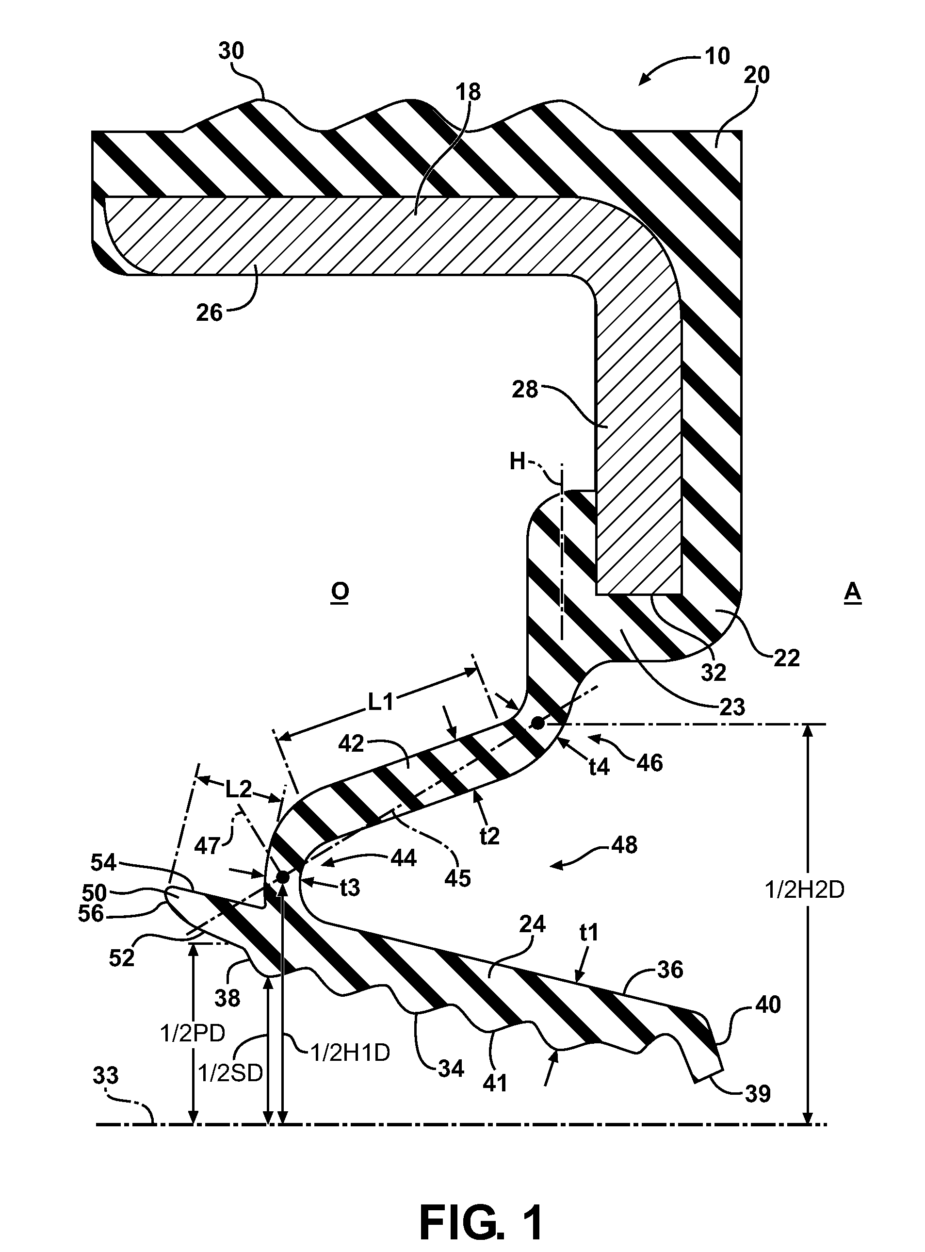
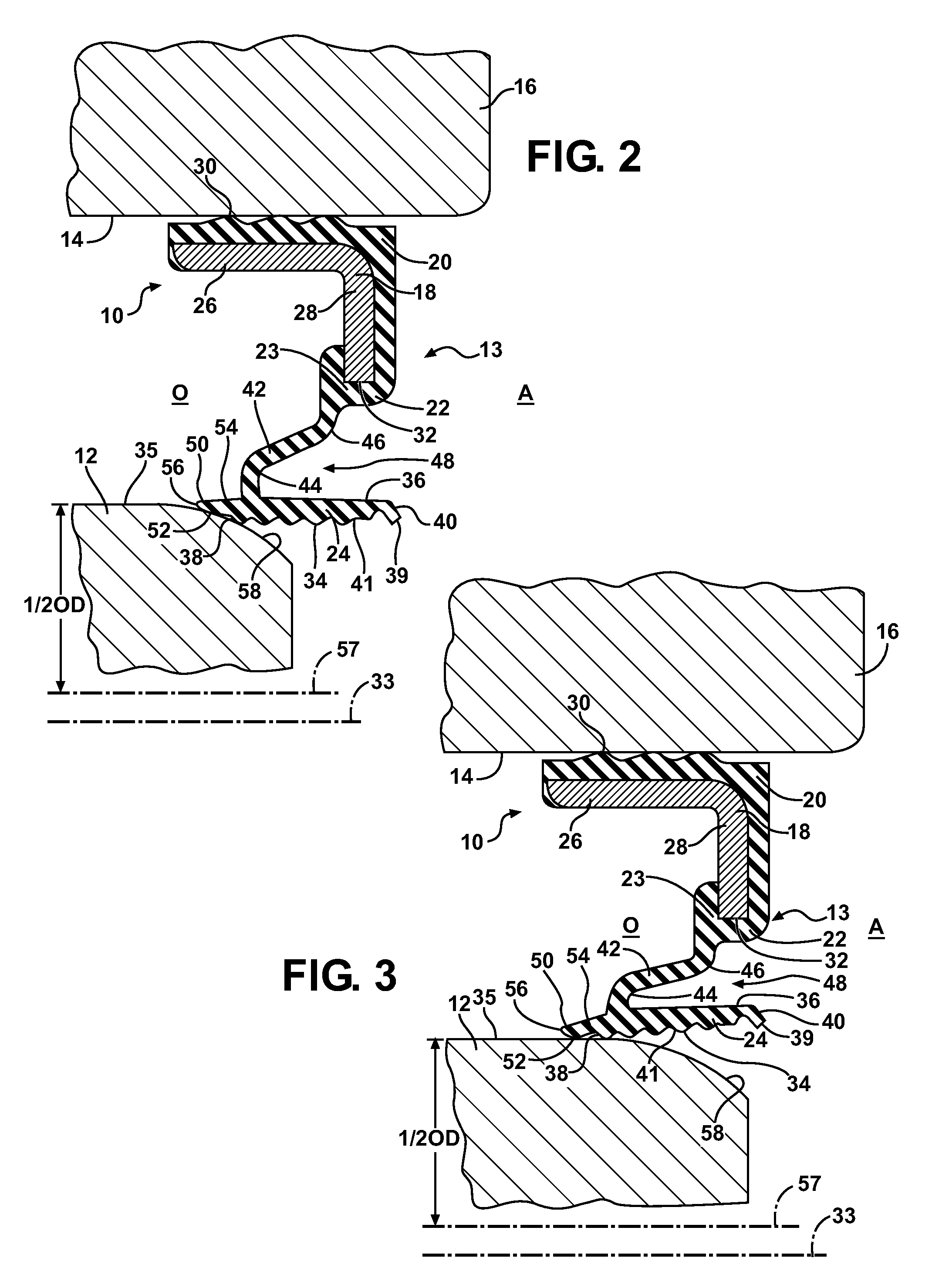
[0027]Referring in more detail to the drawings, FIG. 1 illustrates a radial shaft seal, referred to hereafter as seal 10, constructed in accordance with one aspect of the invention, wherein the seal is suitable for use in a crankcase application, by way of example and without limitation, for sealing about a rotatable shaft 12 in a radial shaft seal assembly 13 (FIGS. 2-4) extending through a bore 14 in the crankcase 16 in which the seal 10 is installed. Otherwise, the seal 10 can be installed into a carrier housing, whereupon the carrier housing and seal 10 can be attached to the engine. The seal 10 has an oil side O and an axially opposite air side A, in relation to the orientation of the seal 10 when installed, with the oil side O facing to the interior of the crankcase 16 and the air side A facing to the outside environment. The seal 10 includes a mounting portion, such as a case, also referred to as core or collar 18, provided as a metal annulus or ring structure with an elastom...


PUM

PropertyMeasurementUnit
Fractionaaaaaaaaaa
Fractionaaaaaaaaaa
Fractionaaaaaaaaaa

Abstract

A radial shaft seal configured for receipt in a housing and about a shaft to sealingly isolate an air side of the seal from an oil side of the shaft seal is provided. The seal includes a mounting portion and a seal lip having an annular sealing surface extending between an oil side end and a free air side end. An annular bridge is connected to the oil side end of the seal lip by a first hinge and to the mounting portion by a second hinge. The bridge extends from the first hinge to the second hinge in radially overlying relation to the seal lip. A projection extends from the first hinge away from the bridge toward the oil side of the seal to prevent the seal lip from inverting during the oil-side installation assembly.

Description

CROSS-REFERENCE TO RELATED APPLICATION[0001]This application claims the benefit of U.S. Provisional Application Ser. No. 61 / 147,938, filed Jan. 28, 2009, and also the benefit of U.S. Provisional Application Ser. No. 61 / 226,368, filed Jul. 17, 2009, which are both incorporated herein by reference in their entirety.BACKGROUND OF THE INVENTION[0002]1. Technical Field[0003]This invention relates generally to dynamic oil seals of the type for creating a fluid tight seal between a rotating shaft and a housing.[0004]2. Related Art[0005]Dynamic radial shaft oil seals are designed to have a so-called “oil side” of the seal and an “air side.” These designations pertain to the orientation of the seal when installed, with the oil side facing the interior of the housing and in communication with the oil, whereas the air side faces outwardly and is exposed to the air.[0006]There are at least two different ways in which a radial shaft oil seal can be installed. An “air side installation” is one in...

Claims


Application Information

Patent Timeline
IPC IPC(8): F16J15/32B23P19/02
CPCF16J15/3224Y10T29/53657F16J15/3268F16C3/14F16J15/16F16J15/18F16J15/32
Inventor SEDLAR, BRENT R.TOTH, DAVID M.NOTEBOOM, II, RONALD M.
Owner TENNECO
Why Eureka
Try Eureka