
Recording apparatus and method of controlling air releasing valve in drying section of the recording apparatus

Inactive Publication Date: 2010-07-29
SEIKO EPSON CORP
View PDF10 Cites 22 Cited by
  • Summary
  • Abstract
  • Description
  • Claims
  • Application Information

AI Technical Summary

Benefits of technology

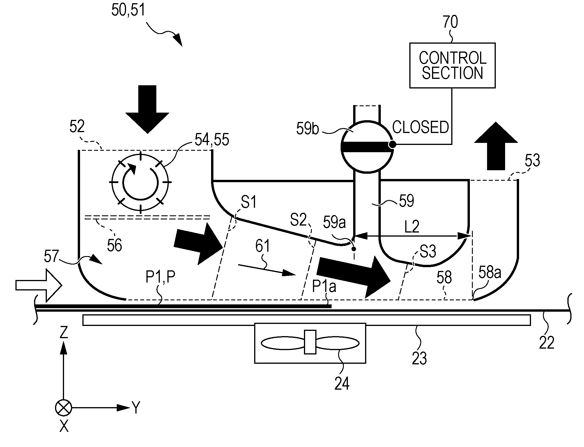
[0006]An advantage of some aspects of the invention is that it provides a recording apparatus which reduces fluttering of the tailing end of a recording medium in a feeding direction caused by air when drying ink on the recording medium with the air generated therein, and a method of controlling a drying section in the recording apparatus.

Problems solved by technology

Moreover, when the hot air which includes factors spanning from an upstream side to a downstream side in a sheet feeding direction is blown onto a sheet, in other words, if the hot air is obliquely blown onto the surface of the sheet from the tailing end side to the leading end side of the sheet, there is problem that the hot air may go into the gap between the tailing end of the sheet and a supporting portion which supports the sheet when the tailing end of the sheet passes through the drying unit.
In this case, there is a problem in that the tailing end of the sheet flutters because the tailing end is separated from the supporting portion and receives the hot air.
In addition, the fluttering causes the problem of so called paper jamming.
Furthermore, when the flow rate of the air that comes into contact with the recording medium gets higher as it advances in the downstream side in the feeding direction, the problem is raised that the tailing end of the recording medium flutters.

Method used


Image

  • Recording apparatus and method of controlling air releasing valve in drying section of the recording apparatus
  • Recording apparatus and method of controlling air releasing valve in drying section of the recording apparatus
  • Recording apparatus and method of controlling air releasing valve in drying section of the recording apparatus

Examples


other embodiment 1

[0129]FIG. 7 is a side view schematically showing a hot air unit according to other embodiment 1.

[0130]As shown in FIG. 7, the hot air unit 81 according to the other embodiment 1 includes a branching path 85, an air outlet 82, a suction fan 83 as an air generating unit 54.

[0131]Since other members have the same configuration as in the embodiment described above, the same reference numerals are given thereto and the explanation thereof will not be repeated.

[0132]Among these, the branching path 85 is provided so as to branch off from the main line of a flow passage 86 within the range where the opening portion 58 in the middle of an air guiding portion 84 extends in the feeding direction Y same as the above-described embodiment. In addition, the branching path 85 has an air-opening valve 59b same as the above-described embodiment. One feature that is different from the above-described embodiment is that the downstream side of the air flowing direction in the branching path 85 is conne...

other embodiment 2

[0135]FIG. 8 to FIG. 12 are side views schematically showing the operation of the hot air unit according to other embodiment 2. Among these, FIG. 8 shows a state where the leading end of a sheet is positioned within the range where the opening portion extends in the feeding direction. FIG. 9 shows a state where the tailing end of the sheet reaches the position of a first branching point in the feeding direction. Furthermore, FIG. 10 shows a state where the tailing end of the sheet reaches the position of a second branching point in the feeding direction. FIG. 11 shows a state where the tailing end of the sheet reaches the position of a fourth position in the feeding direction. FIG. 12 shows a state where the tailing end of the sheet reaches the position of the downstream end of the opening portion in the feeding direction.

[0136]As shown in FIG. 8 to FIG. 12, the hot air unit 91 according to the other embodiment 2 includes a first branching path 93 to a fourth branching path 96, and ...


PUM


Abstract

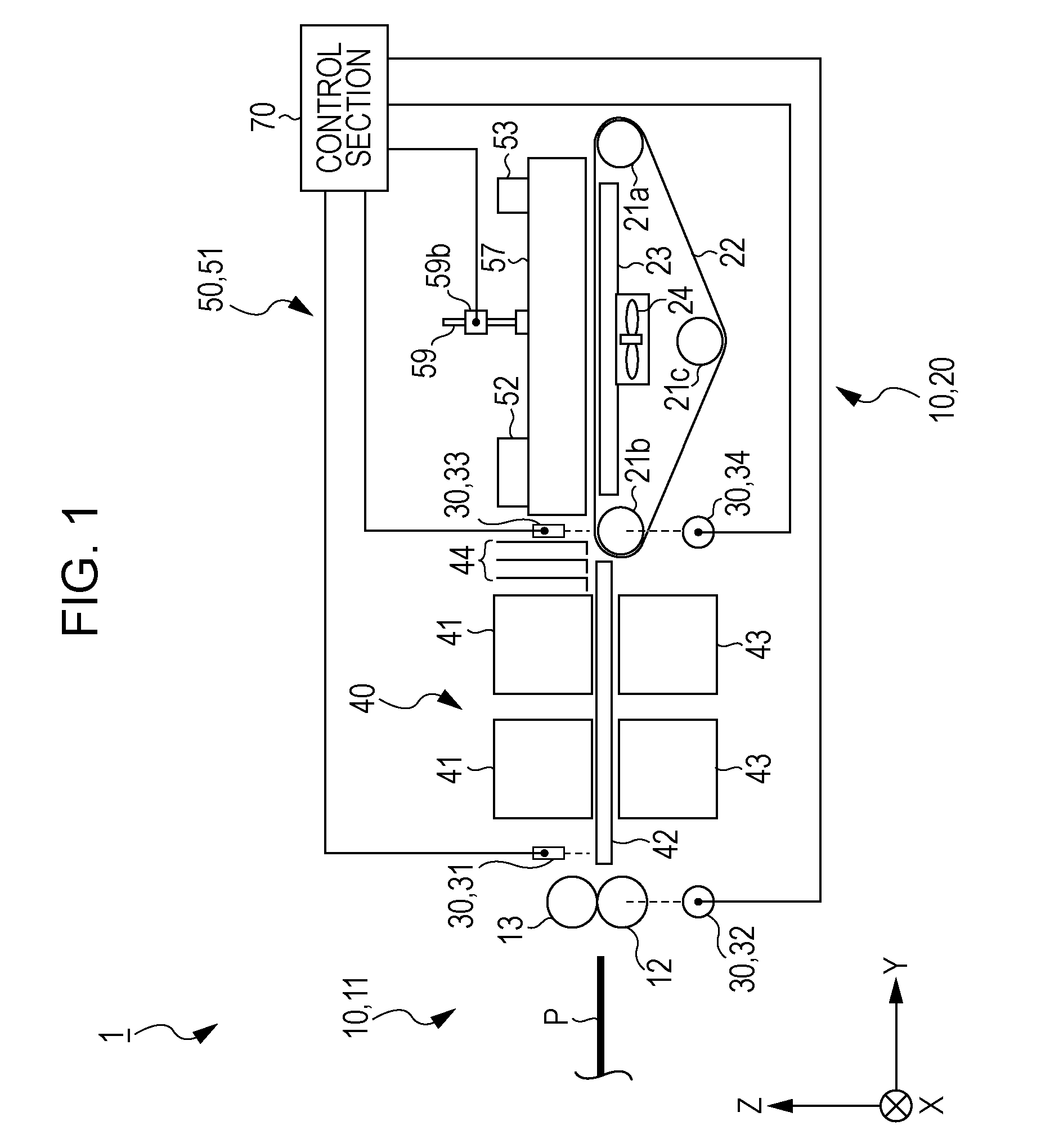
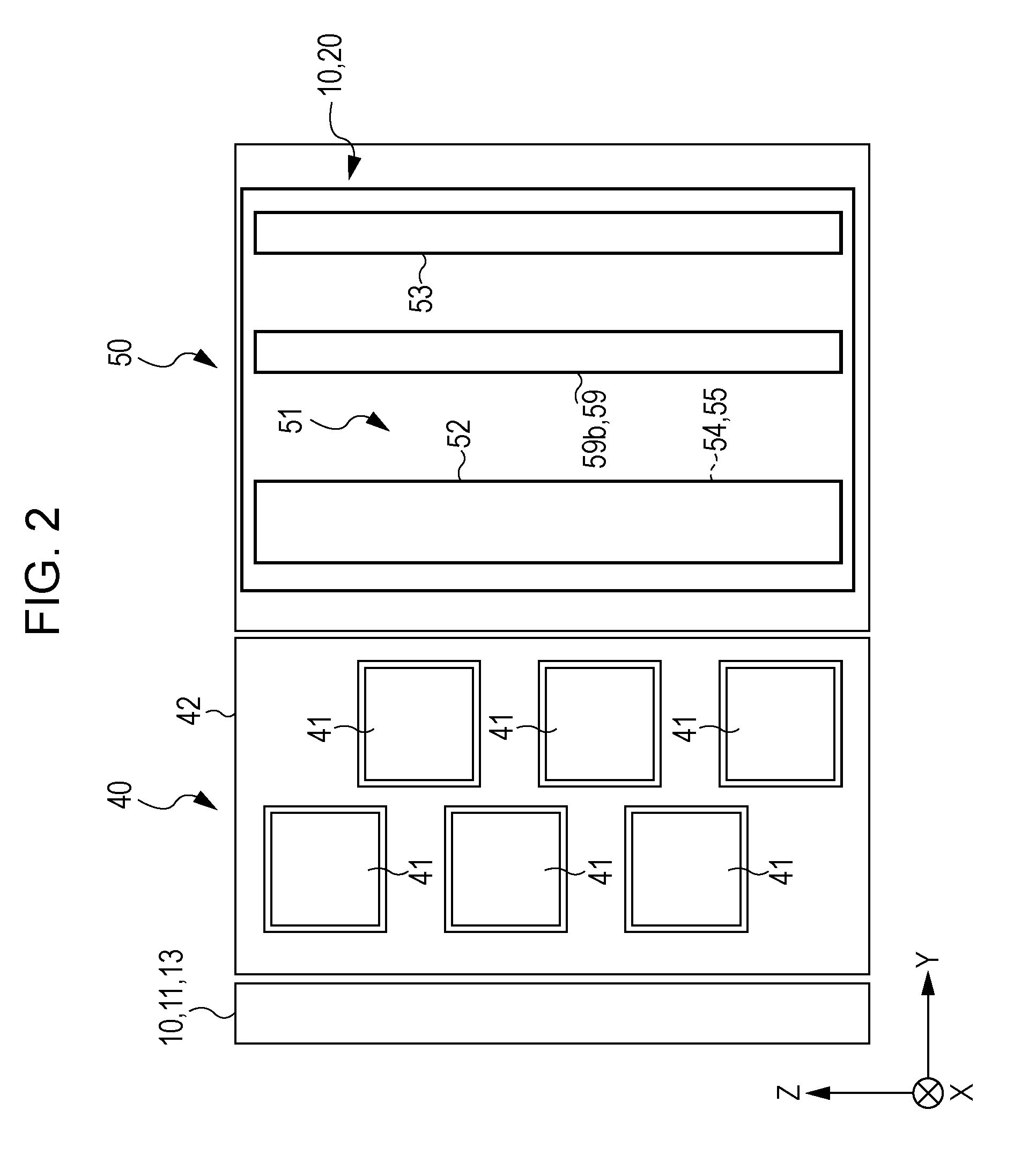
Provided is a recording apparatus comprising recording heads; a medium feeding unit; a position detecting unit; a drying section including an air generating unit and generates air, an air guiding portion, the drying section bringing the air guided by the air guiding portion into contact with the recording medium via an opening portion; a branching path which branches off over the range where the opening portion extends in the feeding direction, branches and guides part of the air flowing from the upstream side to the downstream side in the feeding direction in the air guiding portion of the drying section; an air releasing valve; and a control section which controls the opening or closing of the air releasing valve according to the position of the recording medium.

Description

BACKGROUND[0001]1. Technical Field[0002]The present invention relates to a recording apparatus including recording heads which execute recording by discharging ink onto a recording medium; a medium feeding unit which feeds the recording medium to a downstream side in the feeding direction; and a drying section including an air generating unit which is provided on the downstream side of the recording heads in the feeding direction and generates air, an air guiding portion which guides the air generated by the air generating unit from the upstream side to the downstream side in the feeding direction and forms a flow passage, and an opening portion which extends in the feeding direction in the middle of the flow passage in the air guiding portion so as to face the recording medium, the drying section bringing the air guided by the air guiding portion into contact with the recording medium via the opening portion and drying ink on the recording medium, and a method of controlling the dr...

Claims


Application Information

Patent Timeline
IPC IPC(8): B41J29/38B41J2/01
CPCB41J2/155B41J29/377B41J11/002B41J11/0022
Inventor SHINKAWA, OSAMUHARA, KEIJI
Owner SEIKO EPSON CORP
Learn More