Multiple beamforming method and apparatus

a beamforming method and beam technology, applied in the field of beamforming methods and apparatuses, can solve the problems of poor performance, inability to make full use of the spatial degree of freedom of multiple antennas, performance may be deteriorated, etc., and achieve the effect of reducing feedback overhead and improving the diversity of multiple users

Active Publication Date: 2010-07-29
ELECTRONICS & TELECOMM RES INST +1
View PDF4 Cites 50 Cited by
  • Summary
  • Abstract
  • Description
  • Claims
  • Application Information

AI Technical Summary

Benefits of technology

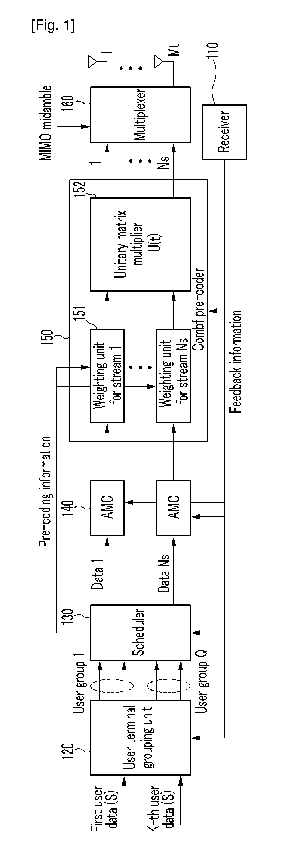
[0016]As described above, embodiments of the present invention use unitary matrixes to improve multiple user diversity gain in slowly varying channel, including the capability of making full use of the spatial degree of freedom by multiple antennas and / or reducing feedback overhead.

Problems solved by technology

However, since OBF generates only one beam every timeslot, the performance is not good, if the number of users is small.
However, since OBF and COBF use multiple transmitting antennas to transmit one stream every timeslot, they cannot make full use of the spatial degree of freedom of multiple antennas.
However, since OMBF should find an appropriate user with a set of multiple beams every timeslot, the performance may be deteriorated if the number of users is small, and PU2RC may not obtain sufficient multiple-user diversity gain in a channel environment in which a change in a channel is small or slow.
However, if the size of the codebook is largecodeword system overhead for the feedback increases when every user terminal feeds the codeword index selected by itself back.
In particular, since the overhead linearly increases as the number of users increases, serious problems may occur when a common channel is used to perform the feedback.

Method used


Image

  • Multiple beamforming method and apparatus
  • Multiple beamforming method and apparatus
  • Multiple beamforming method and apparatus

Examples


Embodiment Construction

[0027]In the following detailed description, only certain exemplary embodiments of the present invention have been shown and described, simply by way of illustration. As those skilled in the art would realize, the described embodiments may be modified in various different ways, all without departing from the spirit or scope of the present invention. Accordingly, the drawings and description are to be regarded as illustrative in nature and not restrictive. Like reference numerals designate like elements throughout the specification.

[0028]In the specification, unless explicitly described to the contrary, the word “comprise” and variations such as “comprises” or “comprising” will be understood to imply the inclusion of stated elements but not the exclusion of any other elements. In addition, the terms “-er”, and “-or” described in the specification mean units for processing at least one function and operation and can be implemented by hardware components or software components and comb...


PUM


Abstract

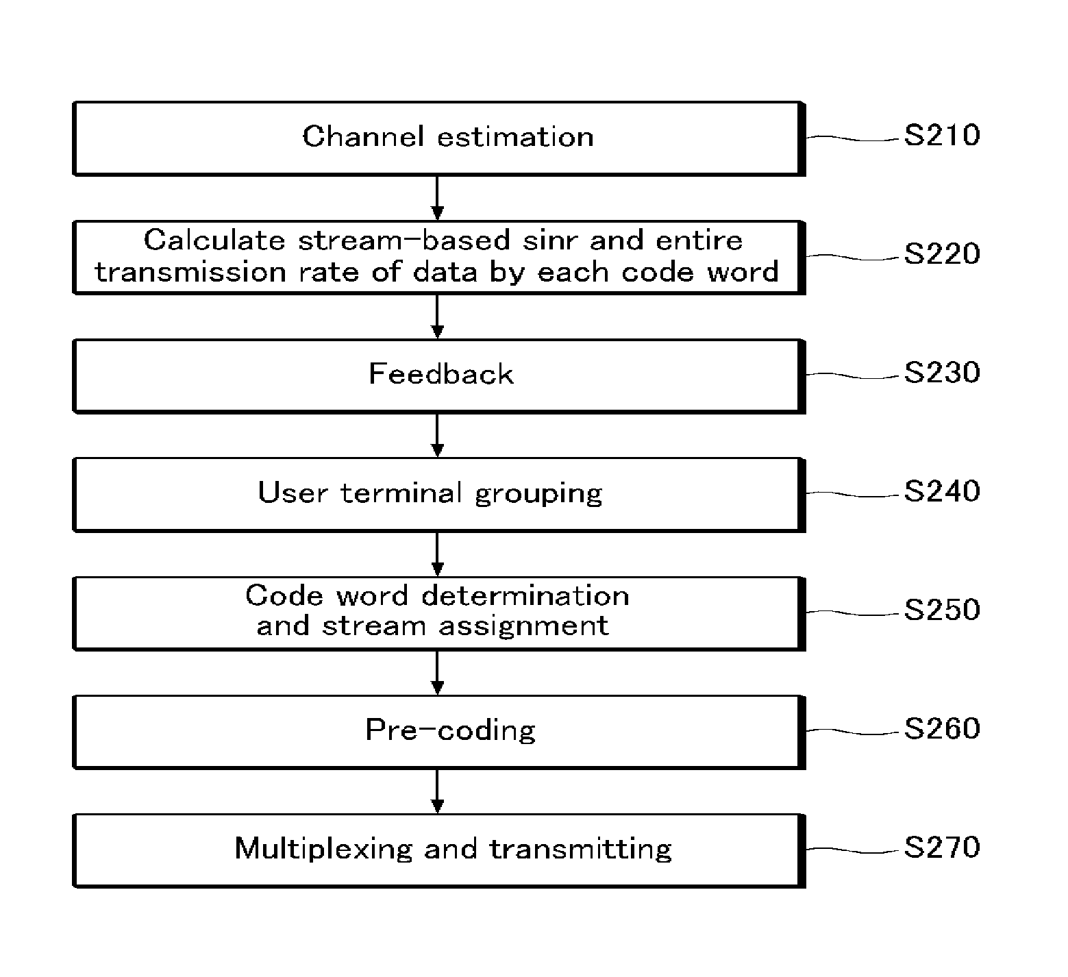
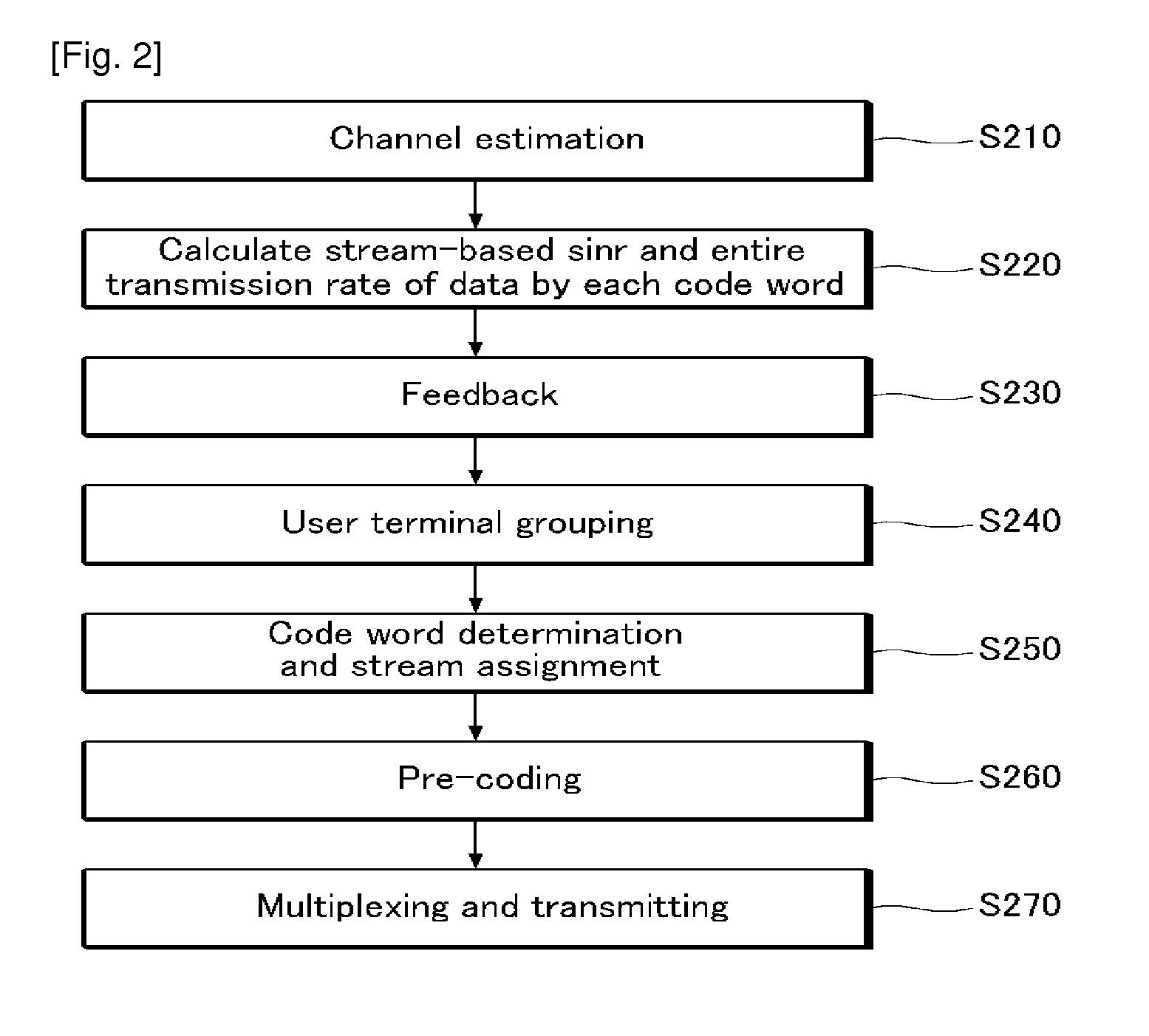
The present invention relates to a beamforming method and apparatus. A beamforming method for use in a base station for transmitting a plurality of streams through a plurality of antennas includes: receiving feedback information including information on a first codeword selected from a codebook including a plurality of codewords from each of a plurality of user terminals; grouping the plurality of user terminals by use of the feedback information from each user terminal; determining a user terminal to which a plurality of streams will be assigned of the plurality of user terminals, and determining a second codeword to be used for beamforming from the codebook by use of the feedback information of each user terminal and grouping information; and multiplying data to be transmitted through the plurality of steams by the second codeword and a unitary matrix.

Description

TECHNICAL FIELD[0001]The present invention relates to a beamforming method and apparatus, and particularly to a multiple beamforming method and apparatus capable of obtaining multiple user diversity gain in a multiple-user environment.BACKGROUND ART[0002]Multiple user diversity gain in a multiple-user environment is obtained by monitoring a change in an independent fading channel for each user and by performing resource allocation when a channel for each user substantially becomes the best state through scheduling. As the change of the channel is increased, the diversity gain is increased. Accordingly, the diversity gain is limited under a channel environment where the change of the channel is small or slow.[0003]Opportunistic beamforming (hereinafter referred to as “OBF”) uses a plurality of transmitting antennas to induce a large and fast change in an arbitrary channel, resulting in multiple-user diversity gain. Based on the possibility that a user for whom a channel is in the bes...

Claims


Application Information

Patent Timeline
Patent Type & Authority Applications(United States)
IPC IPC(8): H04J1/16H04B7/216
CPCH04B7/0617H04B7/0417H04B7/0632
Inventor CHOI, IN-KYEONGKWON, DONG SEUNGKANG, JI WONLEE, CHUNG YONG
Owner ELECTRONICS & TELECOMM RES INST
Why Eureka
Try Eureka