Bumper for a motor vehicle

a bumper and motor vehicle technology, applied in the direction of bumpers, vehicle safety arrangments, transportation and packaging, etc., can solve the problems of reducing the weight and the insurance classification tests tending to contradict each other, and achieve the effect of increasing the stiffness and the loading characteristic in this region

Active Publication Date: 2010-08-05
BENTELER AUTOMOBILTECHNIK GMBH
View PDF14 Cites 11 Cited by
  • Summary
  • Abstract
  • Description
  • Claims
  • Application Information

AI Technical Summary

Benefits of technology

[0010]According to one aspect of the present invention, a bumper for a motor vehicle has a cross member which is attached to longitudinal side rails of the vehicle frame by way of crash boxes. The cross member has a center longitudinal section and ends, which are connected to a corresponding crash box attachment section and an end section. Each crash box attachment section has a U-shaped configuration and a substantially vertical real wall and an upper and a lower leg. The end sections also have a U-shaped cross-section defined by a web and two legs. According to the invention, each web of an end section connects into the rear wall of a crash box attachment section by forming a bulge, which improves the loading characteristic and, in particular, increases the stiffness of the cross member in the region where the cross member is attached to the crash boxes. The impact energy is transmitted to the crash box by way of the cross member with a small bending moment. Due to the increased stiffness, the profile depth of the cross member can be reduced in the outer region, i.e., in the end sections. In addition, the wall thickness of the cross member can be reduced. Altogether, a bumper with an improved loading capacity can be implemented in lightweight construction with optimal weight.
[0011]Advantageously, the bulge projects outward in the direction to the crash box. The web of the end sections is altogether rounded, particularly over the vertical height. This measure also increases the stiffness characteristic and the energy absorption capacity of the bumper.
[0015]The cross member is constructed as a single saucer-shaped or U-shaped piece and is preferably made of sheet steel. The web(s) of the cross member is / are arranged on the side of the bumper facing the motor vehicle. The front side of the cross member is closed off with a cover plate, which is joined to the front webs. The joints can be implemented as spot joints and prepared by, for example, spot welding, punch-riveting or similar joining techniques. Preferably, the cover plate is connected to the front webs with an adhesive. In this way, a further reduction in weight and increase in stiffness can be attained. This measure provides additional benefits in that the adhesive layer has an insulating function and prevents contact corrosion between the cross member and the cover plate. The use of non-galvanized sheet metal, in particular hot-formed and hardened steel profile, now becomes possible or is at least made easier. Advantageously, use of an adhesive is favored for connecting a cross member and a cover plate made from a lightweight metal, for example sheet aluminum, or from a combination of different materials, for example, when the cross member is made of sheet steel and the cover plate is made of a lightweight metal.
[0017]In addition, the vertical height of the web of the center longitudinal section can vary. In particular, the web can be higher and wider at the center of the center longitudinal section than in the regions adjacent to the attachment sections. Moreover, regions of the front sections in the center longitudinal section may have chamfers. The chamfers are also provided in the center of the center longitudinal section, thereby increasing the stiffness and the loading characteristic in this region.

Problems solved by technology

However, the required weight reduction and the insurance classification tests tend to contradict one another.

Method used


Image

  • Bumper for a motor vehicle
  • Bumper for a motor vehicle
  • Bumper for a motor vehicle

Examples


Embodiment Construction

[0027]Throughout all the Figures, same or corresponding elements may generally be indicated by same reference numerals. These depicted embodiments are to be understood as illustrative of the invention and not as limiting in any way. It should also be understood that the Figures are not necessarily to scale and that the embodiments are sometimes illustrated by graphic symbols, phantom lines, diagrammatic representations and fragmentary views. In certain instances, details which are not necessary for an understanding of the present invention or which render other details difficult to perceive may have been omitted.

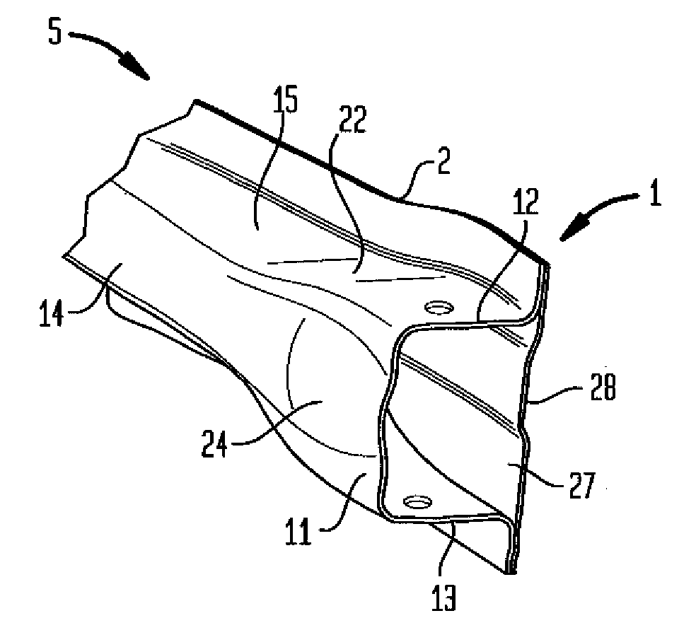
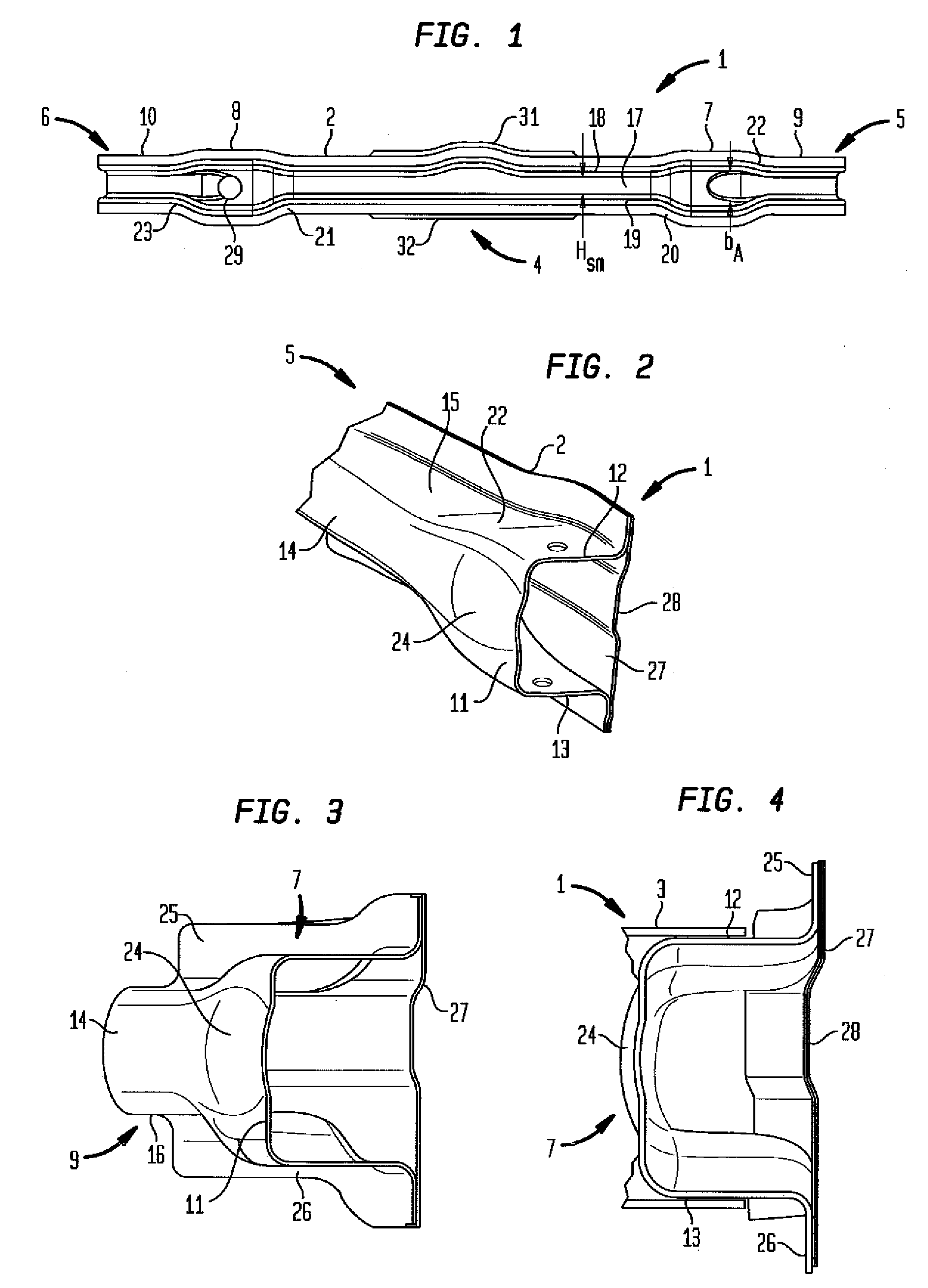
[0028]Turning now to the drawing, and in particular to FIG. 1, there is shown a bumper 1 for a motor vehicle according to the invention. The bumper 1 includes a cross member 2 which can be attached to a side rail of a motor vehicle (not shown). The cross member 2 is attached to the side rails by way of crash boxes 3 which are schematically indicated in FIGS. 4 and 10. The cr...


PUM


Abstract

A bumper for a motor vehicle has a cross member disposed transversely in relation to side rails of a vehicle frame and is supported on the side rails by crash boxes. The cross member includes a central longitudinal section having opposite ends, a crash box attachment section with a substantially vertical rear wall and two legs, and an end section having in cross-section a U-shaped configuration defined by two legs and a web which interconnects the legs and forms an outward-projecting bulge. The bulge is joined with the substantially vertical rear wall of the attachment section.

Description

CROSS-REFERENCES TO RELATED APPLICATIONS[0001]This application claims the priority of German Patent Application, Serial No. 10 2009 006 609.8, filed Jan. 29, 2009, pursuant to 35 U.S.C. 119(a)-(d), the content(s) of which is / are incorporated herein by reference in its entirety as if fully set forth herein.BACKGROUND OF THE INVENTION[0002]The present invention relates to a bumper for a motor vehicle.[0003]The following discussion of related art is provided to assist the reader in understanding the advantages of the invention, and is not to be construed as an admission that this related art is prior art to this invention.[0004]Bumpers are provided as standard equipment on both the front and the rear of motor vehicles to absorb the impact energy caused by minor impacts and to prevent or minimize damage to the actual structural support of the motor vehicle. A bumper typically includes a cross member which can be attached transversely to the side rails by way of crash boxes. The function...

Claims


Application Information

Patent Timeline
Patent Type & Authority Applications(United States)
IPC IPC(8): B60R19/34B60R19/18
CPCB60R19/18B60R2019/182B60R19/34
Inventor MULLER, OLIVERROPER, BURKHARD
Owner BENTELER AUTOMOBILTECHNIK GMBH
Why Eureka
Try Eureka