Electronic lightbar warning device and method of use thereof

a technology of electronic lightbar and warning device, which is applied in the field of remote control of lightbars, can solve the problems of reducing the efficiency of operation of alternators and batteries, affecting the environment, and reducing longevity

Inactive Publication Date: 2010-08-05
LAROSA TOM F
View PDF13 Cites 44 Cited by
  • Summary
  • Abstract
  • Description
  • Claims
  • Application Information

AI Technical Summary

Problems solved by technology

Lighting systems may be hardwired into emergency vehicles creating a large demand for electrical power whereby alternators and batteries may experience decreased efficiency in operation and diminished longevity.
Further, inefficiencies of hardwired lighting systems in use may cause excessive idling of vehicles leading to unnecessary burning of fossil fuels thereby damaging the environment and creating a danger to persons operating those vehicles.
In addition, should a hardwired system fail the entire vehicle must often be taken out of service until repairs can be made.
In an effort to compensate for large electric loads being placed on the vehicle, vehicles may be required to be equipped with higher horsepower motors, which may lead to increased maintenance and decreased reliability.
Hardwired lighting systems may also occupy a substantial volume as wires are routed through and subsequently concealed in vehicles.
Problems exist when attempting to pass wires through congested areas such as doors and headliners.
It is difficult, time-consuming, expensive and labor-intensive to run wires past items such as side curtain air bags, and to drill access holes in roofs.
Wires may impede the proper operation of air bags and other such accessories causing undue danger to drivers and occupants of these vehicles.
Vehicles with access holes in roofs, permitting wiring to pass from the interior to the exterior, may experience lower resale rates and / or alternatively further labor expenditures to conceal such holes after the vehicle is surplused.
Lighting systems of this nature do not lend themselves to portable usage due to the method by which they are mounted and wired.
Further, bulky control heads to operate such systems may limit valuable interior space of the vehicle.

Method used


Image

  • Electronic lightbar warning device and method of use thereof
  • Electronic lightbar warning device and method of use thereof
  • Electronic lightbar warning device and method of use thereof

Examples


Embodiment Construction

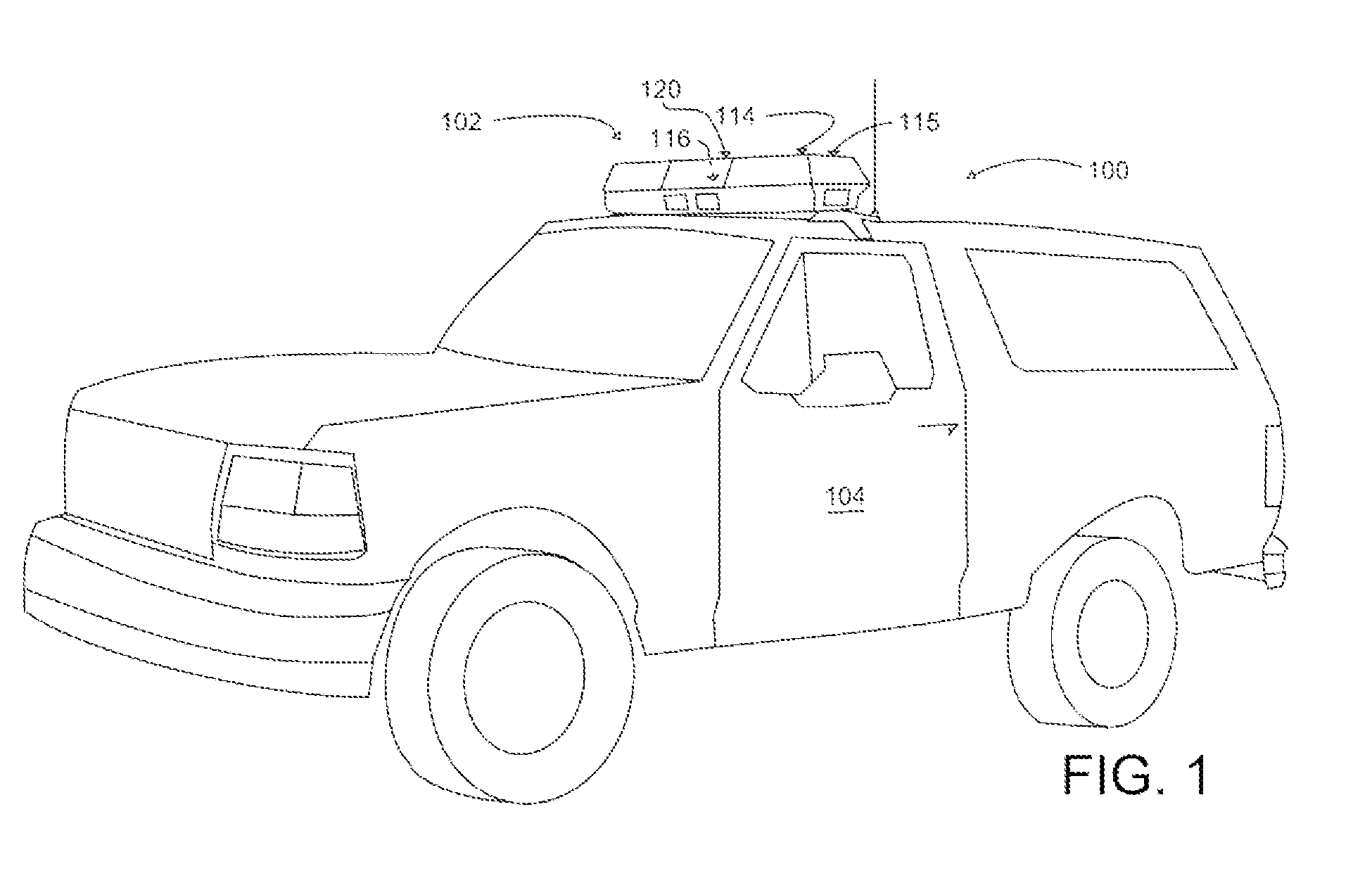
[0017]Referring now to FIG. 1, showing a perspective view, illustrating emergency lighting system 100 in use on emergency vehicle 104, according to an embodiment of the present invention.

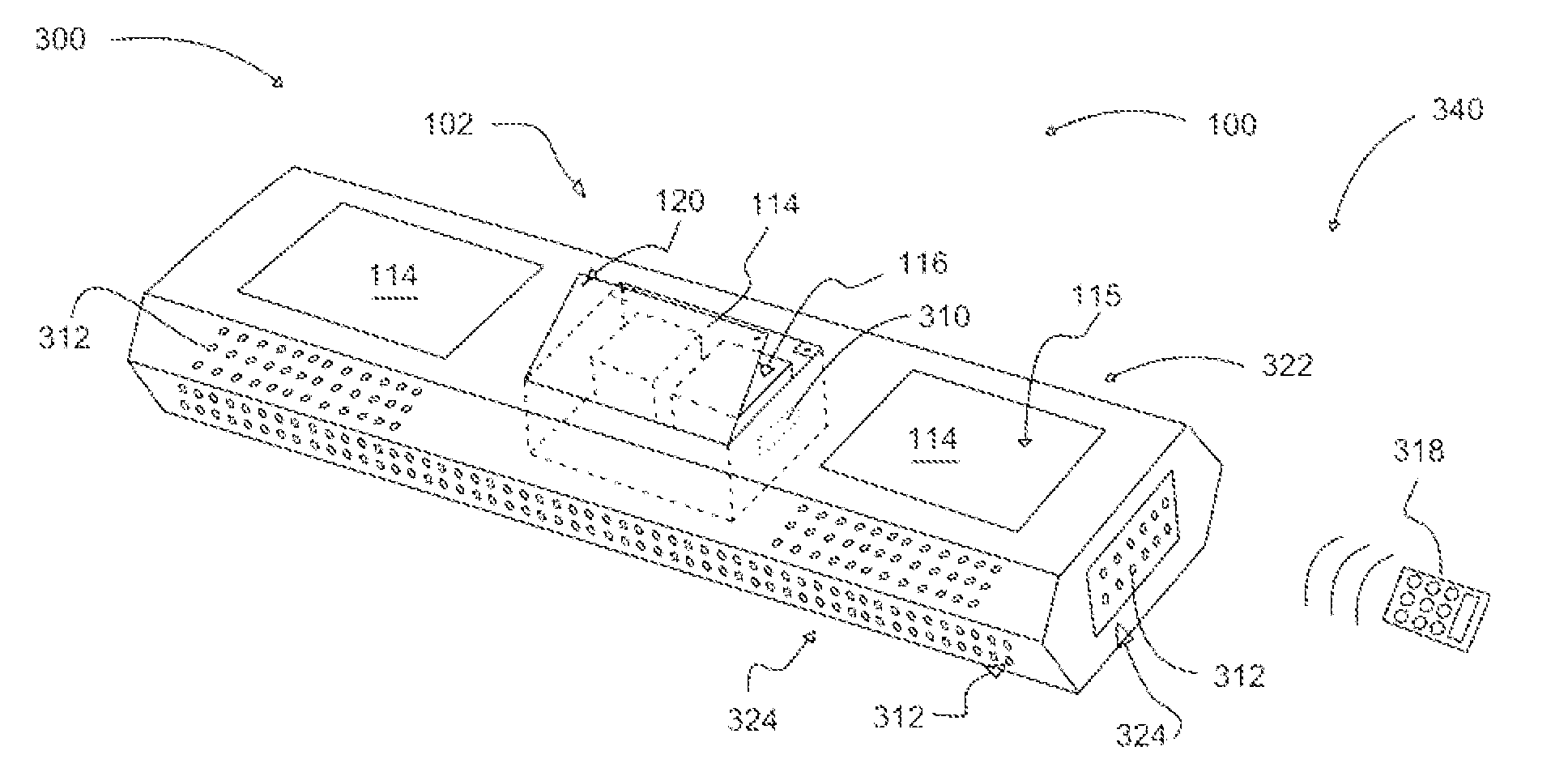
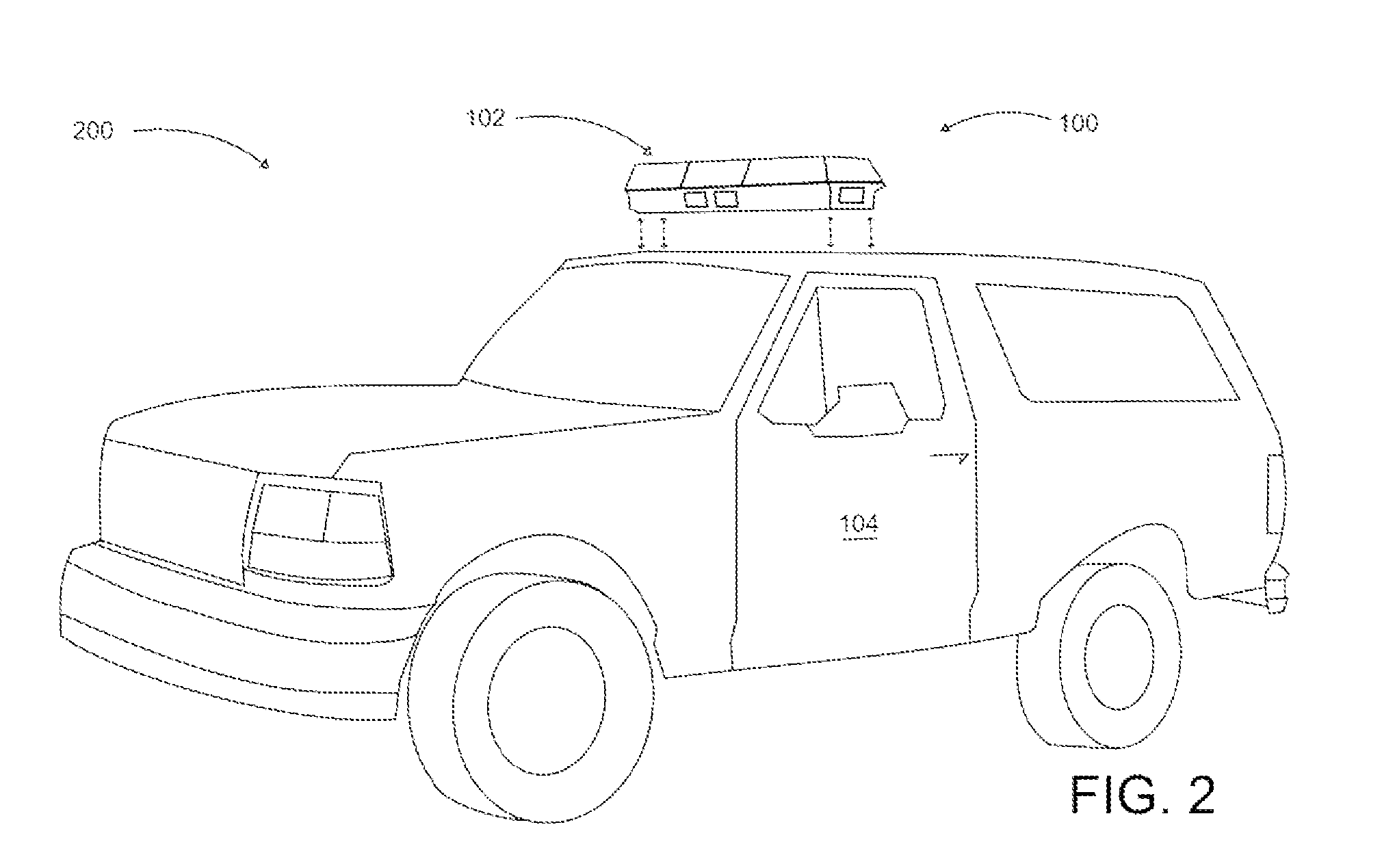
[0018]Emergency vehicle 104 lighting may utilize several visual warning devices, which may include at least one light bar 102 and / or at least one beacon, fitted to at least one emergency vehicle 104. Emergency lighting system 100 is designed to be a warning device used when a driver of an emergency vehicle 104 wishes to convey to other road users the urgency of their journey, to provide at least one warning of at least one hazard when stationary, or in the case of law enforcement as a means of signaling at least one driver to stop for at least one interaction with at least one officer, or serving as a location or status system.

[0019]Emergency lighting system 100 preferably comprises at least one light bar 102, as shown, which may or may not be used in combination with sirens in order to maximize its...


PUM


Abstract

A warning device comprising a lightbar, a programmable chip for controlling LED lights, a controller, and a rechargeable battery. The lightbar is removably coupled to the emergency vehicle or another object such as a road block, where a dangerous situation exists, to warn persons of a hazard. Rechargeable batteries are recharged by solar panels on the lightbar. Rechargeable batteries are used to power the warning device. The programmable chip for controlling the LED is linked wirelessly to the controller, a remote control. The lightbar may be activated by a remote control from inside or outside the vehicle or from a base station to perform a variety of tasks. Warnings may be transmitted from the lightbar using visual and audio signals. Visual signals may include flashing at various speeds and intensities in various colors, text messages and other warning signals to advise persons of dangers in an effort to promote safety.

Description

CROSS-REFERENCE TO RELATED PATENT APPLICATIONS[0001]This patent application claims the benefit of priority to U.S. Provisional Patent Application No. 61 / 150,075, filed Feb. 5, 2009, and entitled, “Lightbar Systems,” which is incorporated in its entirety herein by reference.BACKGROUND OF THE INVENTION[0002]1. Field of the Invention[0003]The present invention relates generally to the field of lighting and more specifically relates to remote-controlled lightbars which can be used particularly for emergency vehicles.[0004]2. Description of the Related Art[0005]Emergency lighting is required in many situations to provide warnings or notice to individuals, vehicles and the like of any dangerous situations that may be present. Lighting systems may be hardwired into emergency vehicles creating a large demand for electrical power whereby alternators and batteries may experience decreased efficiency in operation and diminished longevity. Further, inefficiencies of hardwired lighting systems i...

Claims


Application Information

Patent Timeline
Patent Type & Authority Applications(United States)
IPC IPC(8): B60Q1/52G09F9/33G08B5/22
CPCB60Q1/2611B60Q2900/30B60Q1/2615
Inventor LAROSA, TOM F.
Owner LAROSA TOM F
Why Eureka
Try Eureka