Lateral access blanket

a blanket and lateral technology, applied in the field of convective heating blankets, can solve the problem of no convective heating blankets on the mark

Inactive Publication Date: 2010-08-05
SMITHS MEDICAL ASD INC
View PDF10 Cites 15 Cited by
  • Summary
  • Abstract
  • Description
  • Claims
  • Application Information

AI Technical Summary

Benefits of technology

[0006]A flap that is an extension from the other side of the upper body portion away from the longitudinal side edge leg portion extends from the upper body portion to the length of the longitudinal leg portions. The outer side edge of the flap is a continuation of the longitudinal side edge of the upper body portion, while the inner side edge of the flap is removably connected to the longitudinal side edge of the leg portion that extends from approximately the middle of the distal section of the upper body portion, so that the flap can be separated from the longitudinal leg portion. For further discussion, this longitudinal leg portion may be referred to as the mid-section longitudinal leg portion. To effect the removable attachment, spaced cuts are made along the common seal between the flap and the edge of the longitudinal leg portion. Once separated from the mid-secti

Problems solved by technology

But currently there are no convective warming blankets in the market that would allow a surgeon to gain access to the lateral side of a p

Method used


Image

  • Lateral access blanket
  • Lateral access blanket
  • Lateral access blanket

Examples


Embodiment Construction

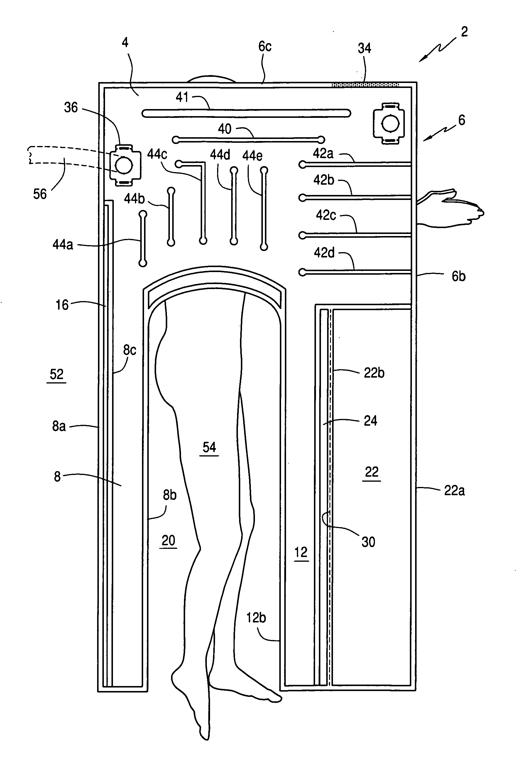
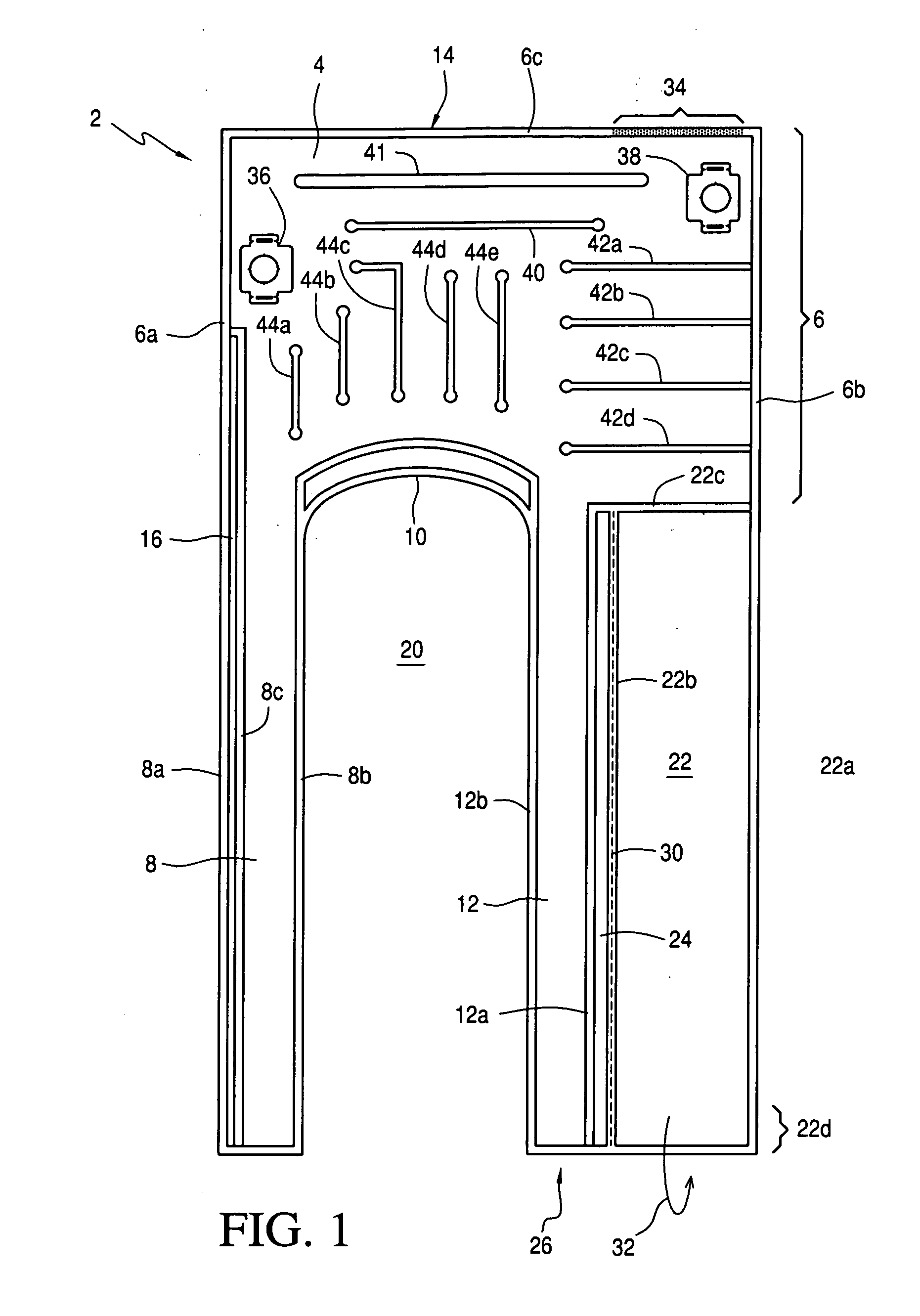
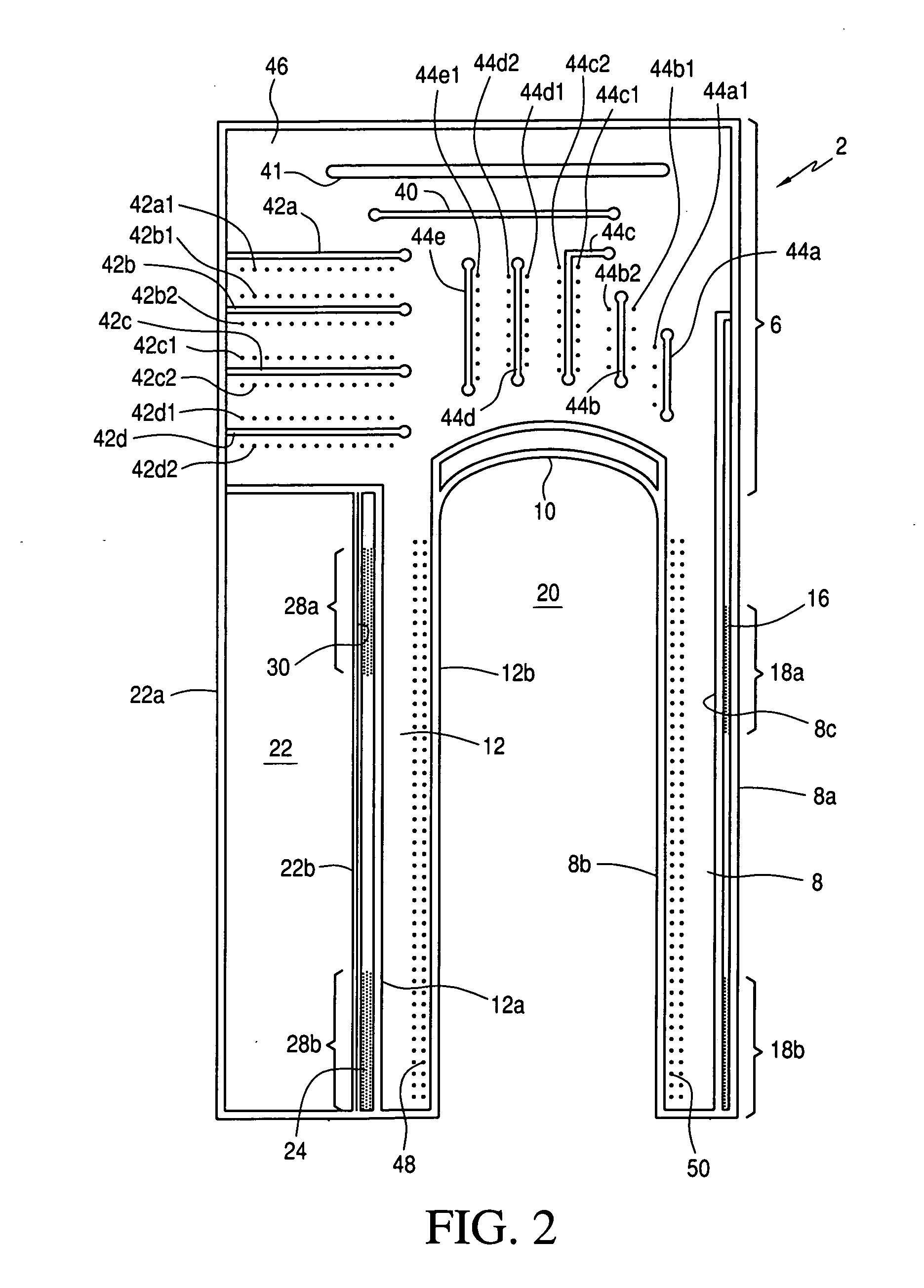
[0017]With reference to FIG. 1, an embodiment of the present invention blanket 2 is shown to include an inflatable structure 4 having an upper body portion 6, a first leg portion 8 that extend longitudinally from a distal end 10 of the upper body portion 6, and another leg portion 12 that also extends from the distal portion 10 of the upper body portion 6. Structure 4 is made up of two air impermeable sheets, the bottom sheet shown in FIG. 2, that are bonded at their respective peripheral edges 14.

[0018]With reference to the orientation of the blanket as shown in FIG. 1, leg portion 8 is shown to extend from the distal end of upper body portion 6 at its left side, and its left edge 8a is a continuation of the left edge or seal 6a of the upper body portion 6. In other words, a continuous seal runs longitudinally from the proximal edge of the upper body portion 6 to the distal edge of the leg portion 8, per shown on the left side of blanket 2. It should be noted that even thought the ...


PUM


Abstract

A convective warming blanket is configured to have an upper body portion and two leg portions that extend from a distal end of the upper body portion. The leg portions are separated by a space sufficient to expose a lateral side of a patient covered by the blanket. A flap separable from the leg portion that extends from the mid-section of the upper body portion may be used to securely wrap around the extended arms of the patient, who is lying on his side. Adhesive tapes are provided on the outside edges of the leg portions to secure the blanket to the surface onto which the patient lies. Apertures are appropriately formed at the sheet that comes into contact with the patient at the upper body portion and along the respective inner side edges of the leg portions so that both the upper body and the exposed lower body of the patient are warmed by heated air. The blanket is designed to have mirror image versions usable for exposing the lateral left side or the lateral right side of the patient.

Description

FIELD OF THE INVENTION [0001]The present invention relates to convective warming blankets, and more particularly relates to a blanket that is designed to allow a clinician or surgeon to gain access to a lateral side of a patient lying on his or her side.BACKGROUND OF THE INVENTION [0002]The use of convective warming blankets for warming a patient during surgery is known. Such convective warming blankets include blankets that are used to fully cover the body a patient, or a part of the patient. There are also underbody blankets onto which a patient lies. But currently there are no convective warming blankets in the market that would allow a surgeon to gain access to the lateral side of a patient to perform a procedure, surgical or otherwise such as for example a hip replacement, that requires the patient to lie on his side.SUMMARY OF THE PRESENT INVENTION [0003]The convective warming blanket of the present invention is configured to be placed over a patient so that a lateral side of ...

Claims


Application Information

Patent Timeline
IPC IPC(8): A61F7/00
CPCA61B19/08A61F2007/0288A61F2007/006A61F7/0097A61B46/00
Inventor PIERRE, JOSEPHSTARR, RACHELSTEC, ALAN
Owner SMITHS MEDICAL ASD INC
Why Eureka
Try Eureka