Vibration shovel of railroad ballast tamping machine

A technology of tamping machine and vibrating shovel, which is applied in the field of vibrating shovel, can solve the problems of reduced work efficiency, easy wear, and influence on the effect of tamping slag, and achieves the effects of improving assembly accuracy, convenient use and installation, and improving wear resistance.

Inactive Publication Date: 2018-02-16
ZHEJIANG PACIFIC MACHINERY CO LTD
View PDF5 Cites 0 Cited by
  • Summary
  • Abstract
  • Description
  • Claims
  • Application Information

AI Technical Summary

Problems solved by technology

[0002] In the prior art, the vibrating shovel of the railway ballast tamping machine is also called a tamping pick. It is mainly composed of the front part of the shovel body and the rear part of the handle. Due to the impact force of ballast slag, the front body of the vibrating shovel is easily damag

Method used


Image

  • Vibration shovel of railroad ballast tamping machine
  • Vibration shovel of railroad ballast tamping machine
  • Vibration shovel of railroad ballast tamping machine

Examples


Embodiment Construction

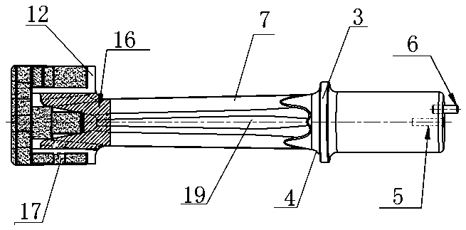
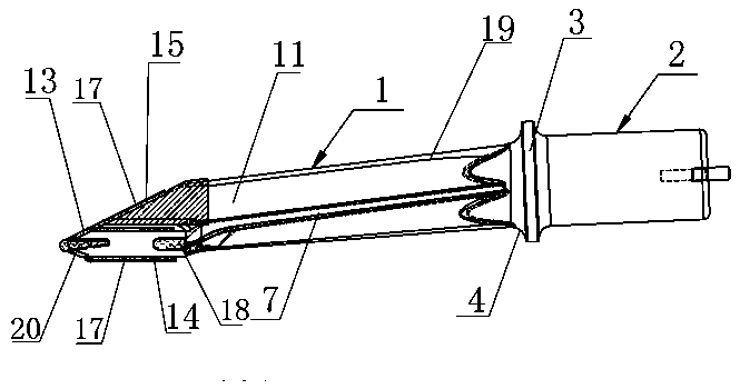
[0012] The invention will be described in detail below in conjunction with the drawings: Figure 1-3 As shown, the vibrating shovel of a railway ballast tamping machine according to the present invention is mainly made of a shovel body 1 in the front section and a cylindrical handle 2 in the rear section. The shovel body 1 includes a and The rear section of the conical handle 2 is a conjoined rod part 11. The front end of the rod part 11 has a plate-shaped shovel head 12 that extends forward and to both sides. The front end surface of the plate-shaped shovel head 12 forms There is a lateral right-angled triangular pointed corner 13, which is composed of a lower bottom plane 14 and an upper inclined plane 15. The upper inclined plane 15 and the rod 11 form the same inclined plane, and the inclined plane of the rod 11 is formed with For the wear resistant layer 16, the upper and lower planes of the plate-shaped shovel head 12 are also formed with a cemented carbide layer 17, and ...


PUM


Abstract

The invention provides a vibration shovel of a railroad ballast tamping machine. The vibration shovel is mainly and integrally composed of a shovel body at a front section and a cylindrical handle ata rear section, wherein the shovel body comprises a rod part connected with the cylindrical handle at the rear section; a platy shovel head which extends to the front and two sides is integrally arranged at the front end of the rod part; a sharp angle with a lateral right triangle is formed on the front end surface of the platy shovel head; the sharp angle is composed of a lower bottom plane and an upper bevel; the upper bevel and the rod part form the same inclined plane; a wear-resistant weld layer is arranged on the inclined plane of the rod part; a hard alloy layer is arranged on the upperplane of the platy shovel head; and two sides of the platy shovel head are at least provided with a piece of hard alloy. The vibration shovel of the railroad ballast tamping machine has the characteristics of being reasonable in structure, convenient to use and install, and capable of improving the assembly accuracy, reducing the product wear, improving the wear resistance of a working surface, prolonging the service life and the like.

Description

Technical field [0001] The invention relates to a vibrating shovel of a railway ballast tamping machine, belonging to the technical field of tamping equipment for tamping rail sleepers. Background technique [0002] In the prior art, the vibrating shovel of a railway ballast tamping machine is also called a shovel. It is mainly formed by connecting the shovel body of the front section and the handle of the rear section. Due to the impact force of the ballast, the front shovel body of the vibrating shovel is easily damaged. Once damaged, it will affect the effect of slagging. However, the currently used vibrating shovel has an unreasonable assembly structure and low surface fastness and wear resistance. As a result, the overall work efficiency is reduced, and the service life is short. Summary of the invention [0003] The purpose of the present invention is to overcome the deficiencies of the prior art, and provide a railway ballast tamping with reasonable structure, convenient u...

Claims


Application Information

Patent Timeline
IPC IPC(8): E01B27/12
CPCE01B27/12E01B2203/12
Inventor 周志建
Owner ZHEJIANG PACIFIC MACHINERY CO LTD
Why Eureka
Try Eureka