A Inclined Coil Heating Furnace

A heating furnace and coil technology, which can be used in heat storage heaters, fluid heaters, lighting and heating equipment, etc., and can solve problems such as difficulty in draining the medium

Active Publication Date: 2017-11-24
THE CHALLENGE PETROCHEM MACHINERY CORP
View PDF5 Cites 0 Cited by
  • Summary
  • Abstract
  • Description
  • Claims
  • Application Information

AI Technical Summary

Problems solved by technology

[0014] The purpose of this application is to avoid the disadvantages of the above-mentioned prior art and specifically aim at the low energy consumption of the medium flow in the ultra-long furnace tube of the heating furnace and the difficulty in discharging the flammable and explosive medium in the furnace tube when the heating furnace is shut down and the solutions to the problems caused , and proposed a slanted coil heating furnace to avoid corrosion of the residual medium in the furnace tube and ensure the safety of maintenance operations

Method used


Image

  • A Inclined Coil Heating Furnace
  • A Inclined Coil Heating Furnace
  • A Inclined Coil Heating Furnace

Examples


Embodiment 1

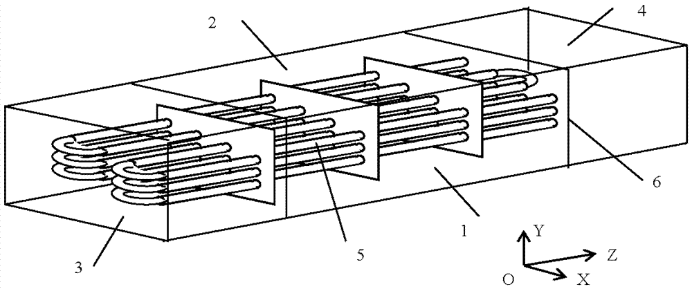
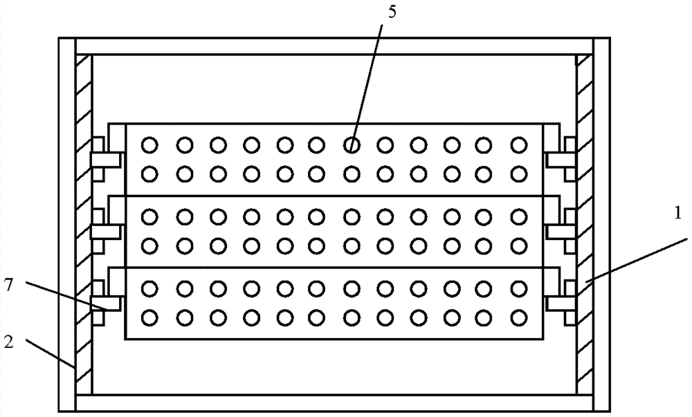
[0055] One of the specific implementations of a slanted coil heating furnace of the present application, according to the variation range of the heat exchange coil temperature in the flue gas flow, each heating furnace is divided into several heat exchange coil modules, stacked The heat insulation and heat preservation furnace walls around all the heat exchange coil modules together can be a whole large furnace wall, or can be independent small furnace walls of each heat exchange coil module. One is a cuboid assembly module.

[0056] The difference from the above-mentioned prior art is that all or part of the furnace tubes in the heat exchange coil module are arranged obliquely downward from the direction of the medium entering the coil 5 to the direction of the medium flowing out of the coil 5 . This application aims at the low energy consumption of the medium flow in the super-long furnace tube of the heating furnace and the difficulty in discharging the flammable and explos...

Embodiment 2

[0058] The second specific implementation mode of a kind of inclined coil heating furnace of the present application, the main technical solution of this embodiment is the same as that of embodiment 1, and the features not explained in this embodiment adopt the explanation in embodiment 1, in This will not be repeated here. The difference between this embodiment and Embodiment 1 is that the traditional vertical column in the prior art is designed with a certain inclination, so that the overall furnace tube in the heat exchange coil module enters the direction of the coil 5 from the medium The direction until the medium flows out of the coil pipe 5 is arranged obliquely downward. The inclined column makes the module support into an inclined structure with one end high and the other end low during installation. When the column returns to the vertical vertical position, the coil 5 in the module will also passively form a structure with one end high and the other end low. incline...

Embodiment 3

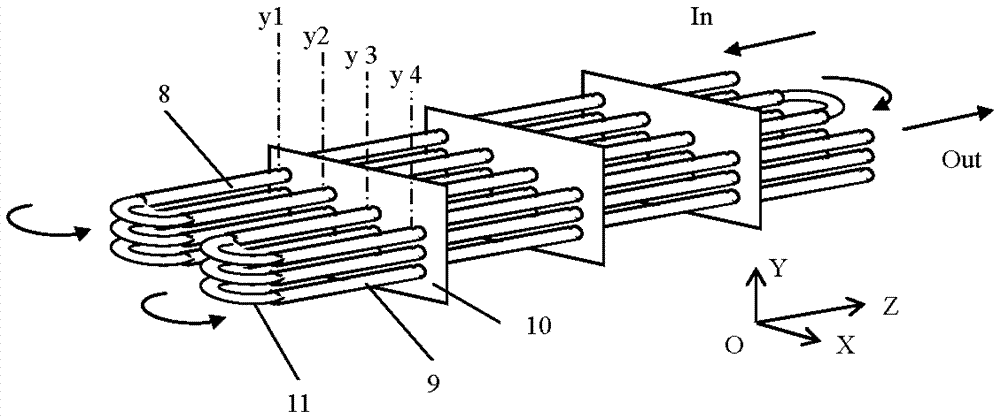
[0061] The third specific embodiment of a slanted coil heating furnace of the present application, the main technical solution of this embodiment is the same as that of embodiment 1, and the features not explained in this embodiment are explained in embodiment 1. This will not be repeated here. The difference between this embodiment and Embodiment 1 is that the furnace tubes located at the same height in the same process in the heat exchange coil module and the coils 5 whose two ends are connected in series through elbows 11, in the coils 5 The furnace tubes are arranged obliquely downward from the direction in which the medium enters the coil 5 to the direction in which the medium flows out of the coil 5 . For details, see image 3 and Figure 4 As shown, in addition to the components mentioned in Embodiment 1, it also includes a furnace tube 8 along the horizontally higher side, a furnace tube 9 along the laterally lower side, a tube plate 10 and an elbow 11 . Among them,...


PUM


Abstract

A heating furnace with obliquely arranged coil pipes; on the basis of the change intervals of the temperature of heat exchange coil pipes during a smoking process, dividing the furnace into a plurality of heat exchange coil pipe modules; a heat exchange coil pipe module comprises a lateral right-side furnace wall (1) and a lateral left-side furnace wall (2), a vertical front end elbow header (3) and a vertical rear end elbow header (4), and coil pipes (5) and a tube sheet (10) arranged inside the furnace walls; the coil pipe (5) comprises a furnace pipe, an elbow (11), and a header, all or part of the furnace pipes inside the heat exchange coil pipe module are arranged obliquely and downward from the direction a medium enters the coil pipe to the direction the medium flows out of the coil pipe. The present structure is beneficial for reducing the energy consumption of the flow of liquids in ultra-long furnace pipes when the heating furnace is in operation and for draining combustible and flammable media when the furnace is stopped, ensuring safe maintenance operations, and preventing corrosion of residual media in the furnace pipes.

Description

technical field [0001] The present application relates to tubular heating furnaces in petroleum refining, petrochemical and other chemical fields, in particular to oblique coil heating furnaces in modularized petrochemical heating furnaces. Background technique [0002] (1) Structural design and function of traditional heating furnace [0003] Heating furnace is the leader in petrochemical industry, including atmospheric furnace, vacuum furnace, hydrogen production furnace, reforming furnace, coking furnace, reforming furnace and cracking furnace. The function of the tube heating furnace is to heat the medium (oil or gas) to the temperature required by the process. [0004] The four sides of the furnace body are surrounded by tall furnace walls. The furnace wall is made of I-shaped steel and other steel frames covered with welded steel plates. The steel plates are distributed with welded insulation nails, and heat insulation and wear-resistant materials are cast between the...

Claims


Application Information

Patent Timeline
Patent Type & Authority Patents(China)
IPC IPC(8): C10G9/20
CPCC10G9/20F24H7/00F28D7/04F28F19/00
Inventor 陈孙艺
Owner THE CHALLENGE PETROCHEM MACHINERY CORP
Why Eureka
Try Eureka