
Dot printing system, dot printing method and computer program

a technology of color printing system and computer program, which is applied in the field of color printing system and dot printing method, can solve the problems of excessive deterioration of image quality, and achieve the effect of reducing the amount of colorants and not excessively deteriorating the image quality of the imag

Active Publication Date: 2010-08-12
SEIKO EPSON CORP
View PDF9 Cites 6 Cited by
  • Summary
  • Abstract
  • Description
  • Claims
  • Application Information

AI Technical Summary

Benefits of technology

[0008]According to this configuration, since the main scanning pass number indicating an order of the main scanning passes to perform dot printing for adjacent main scanning lines in the sub-scanning direction selects a dot position to be extracted on each main scanning line on the basis of the main scanning pass to make adjacent main scanning lines approach each other, it is possible to reduce transmission errors of the sub-scanning accumulated between the main scanning passes to print adjacent main scanning lines. As a result, it is possible to reduce the amount of colorant used using the extracting without excessively deteriorating the image quality.Application 2
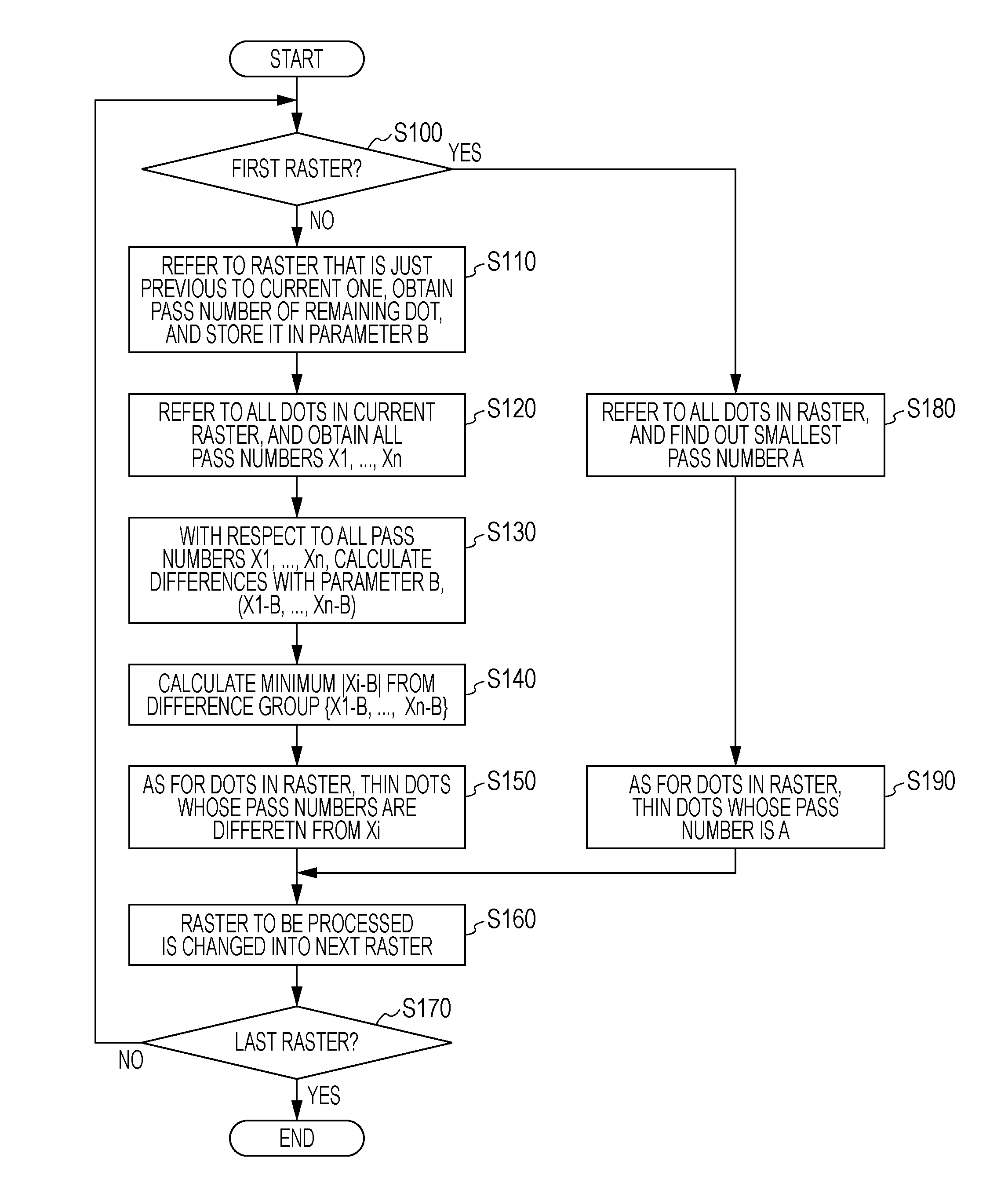
[0014]According to this configuration, following a simple algorithm, it is possible to make the main scanning pass numbers indicating an order of the main scanning passes used to perform dot printing at adjacent main scanning lines as close as possible between the adjacent main scanning lines.

Problems solved by technology

In the method of simply extracting ink dots, however, there is a problem that the image quality is excessively deteriorated due to reduced printing concentration and the like.
Such a problem is not limited to ink jet printers but is common to colorant output devices in which dots are printed on a dot printing medium by outputting colorants.

Method used


Image

  • Dot printing system, dot printing method and computer program
  • Dot printing system, dot printing method and computer program
  • Dot printing system, dot printing method and computer program

Examples


first embodiment

B. First Embodiment

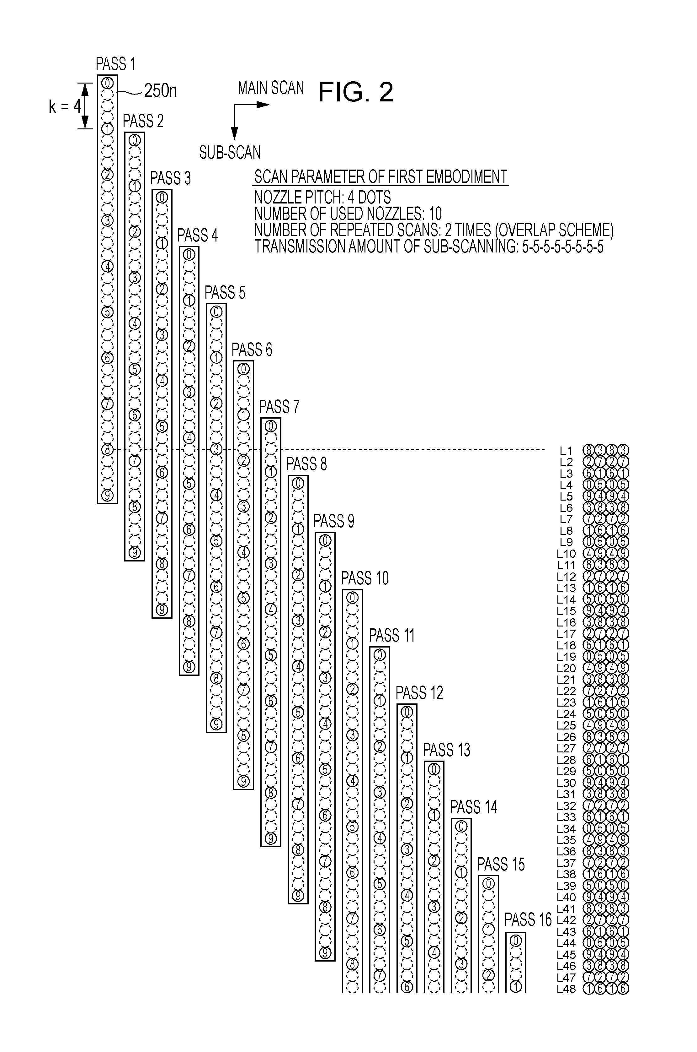
[0038]FIG. 2 is an explanatory view showing a dot printing method in accordance with a first embodiment. Nozzle column 250n mounted in a head unit is shown at the left portion of FIG. 2. The nozzle column 250n has 10 nozzles to discharge one kind of ink (for example, black ink). Nozzle columns for different ink are not shown. While tens to hundreds of nozzles are mounted for each kind of ink in actual printers, a nozzle column having small number of nozzles is described for the sake of convenience of drawing here. Numbers 0-9 attached to each nozzle position are nozzle identification numbers (ID). Pitch k of nozzles in the sub-scanning direction is 180 dpi, for example, and a print pixel pitch is 720 dpi, for example. In this case, nozzle pitch k is 4 [dot]. Generally, it is preferable that pitch k is an integer of 2 or more. The nozzle column 250n prints the dot on the printing medium during the performance of the main scanning in the main scanning direction (lef...

second embodiment

C. Second Embodiment

[0056]FIG. 10 is an explanatory view showing a dot printing method in accordance with a second embodiment. The difference with FIG. 2 is the transmission amount of the sub-scanning only, and other than this, the scanning parameters and apparatus configuration are the same as those of the first embodiment. In a dot printing method of FIG. 10, the transmission amount of sub-scanning is expressed as a repeated pattern of (3 dots, 3 dots, 3 dots, 11 dots). As such, a sub-scanning method that uses the transmission amounts of sub-scanning of plural kinds is referred to as “irregularity transmission”. As shown in FIG. 2, meanwhile, a sub-scanning method using a fixed transmission amount of sub-scanning is referred to “regularity transmission”. Like the regularity transmission, the irregularity transmission is also a scanning method in which dots can be printed in all pixel positions in the zone to be printed.

[0057]FIGS. 11A and 11B are explanatory views showing extracti...

modified example 1

D1. Modified Example 1

[0059]As for characteristics of the dot extracting in consideration of overlap, at least one of characteristics 3 and 4 to be described below may be added, in addition to the characteristics 1 and 2 described above.

[0060]Characteristic 3. The extracting process is performed in the zone printed by the large size dots only.

[0061]Characteristic 4. The dots to be extracted are selected from every other dot in the main scanning direction.

[0062]The characteristic 3 means that the extracting process is not performed in a zone where the medium and small size dots are used. The reason is that since the large size dot makes a large overlap with adjacent dots, deterioration of image quality does not occur excessively even though some of large size dots are extracted. Meanwhile, the medium and small size dots tend to make the image quality deteriorate when they are extracted since the medium size dot is slightly overlapped with adjacent dots and the small size dot is hardl...


PUM


Abstract

A printing apparatus includes an extracting processor that performs an extracting process in which dots are not printed at the main scanning passes performed once or more and less than N times, in a case that the dot printing is completed with respect to a first main scanning line by the main scanning passes performed N times (N is an integer of 2 or more), wherein the extracting processor performs the extracting process such that a first main scanning pass number indicating an order of the main scanning passes in which dots are printed with respect to the first main scanning line and a second main scanning pass number indicating an order of the main scanning pass in which dots are printed with respect to the second main scanning line adjacent to the first main scanning line in the sub-scanning direction, approach each other.

Description

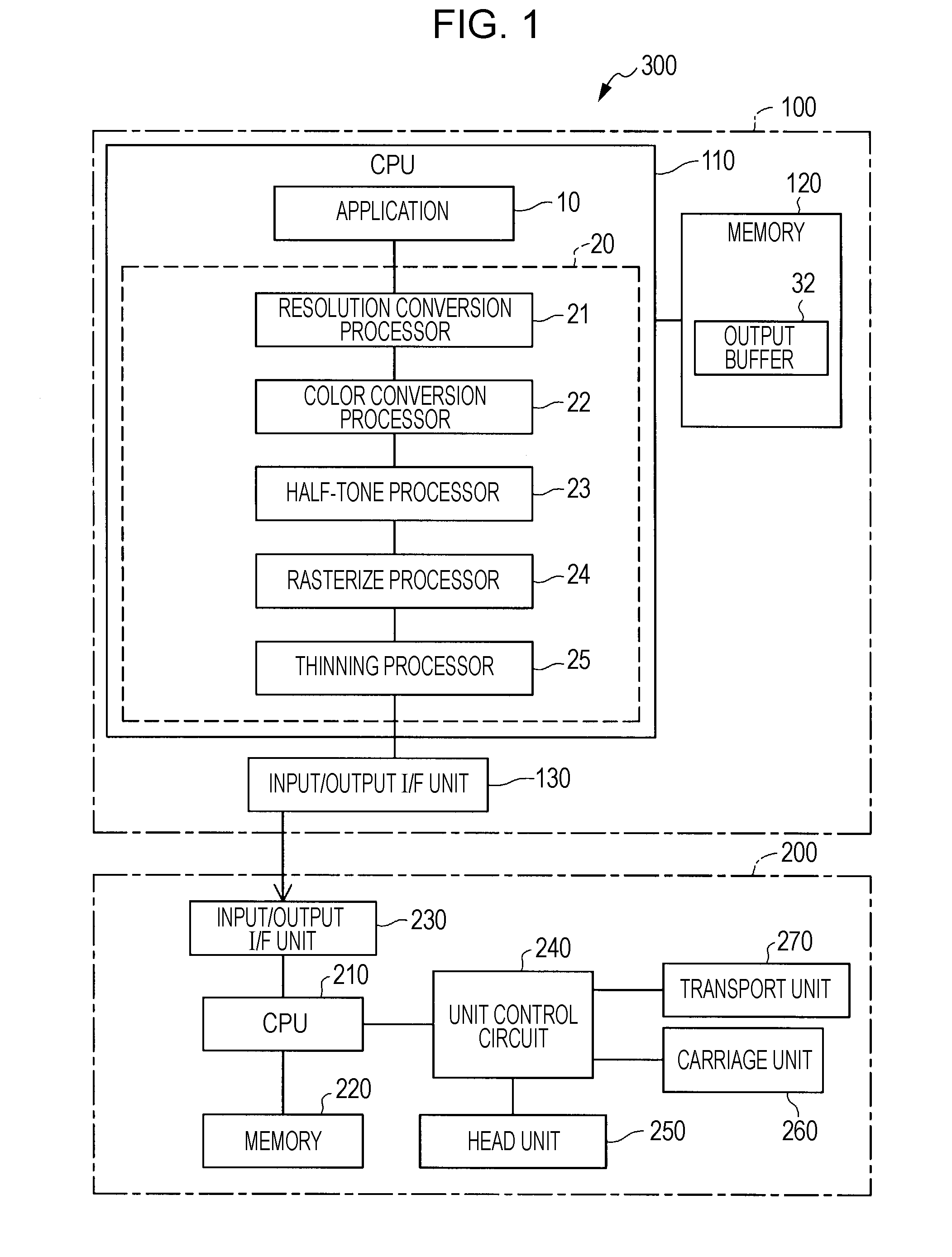
BACKGROUND[0001]1. Technical Field[0002]The present invention relates to a technology in which dot printing is performed by outputting colorants.[0003]2. Related Art[0004]A typical device for performing dot printing by outputting colorants is an ink jet printer. In an ink jet printer, it is desirable to reduce the amount of ink used as much as possible thereby improving cost performance. In order to reduce the amount of ink used, the use of a method of extracting ink dots is known (for example, JP-A-2001-30522).[0005]In the method of simply extracting ink dots, however, there is a problem that the image quality is excessively deteriorated due to reduced printing concentration and the like. Such a problem is not limited to ink jet printers but is common to colorant output devices in which dots are printed on a dot printing medium by outputting colorants.SUMMARY[0006]An advantage of some aspects of the invention is that a technology capable of reducing the amount of colorants for use ...

Claims


Application Information

Patent Timeline
IPC IPC(8): B41J29/38
CPCB41J2/2132G06K15/107B41J29/38
Inventor SAITO, TOSHIKI
Owner SEIKO EPSON CORP
Learn More