
Image forming apparatus

a technology of forming apparatus and forming plate, which is applied in the direction of electrographic process apparatus, instruments, optics, etc., can solve the problems of deterioration of toner, damage of image bearing member, and rubbing force of contact nip on toner on the developer carrying member, etc., to achieve sufficient image density, free from foggy background production, and long-term usability

Inactive Publication Date: 2010-08-12
CANON KK
View PDF6 Cites 2 Cited by
  • Summary
  • Abstract
  • Description
  • Claims
  • Application Information

AI Technical Summary

Benefits of technology

[0011]Accordingly, it is a principal object of the present invention to provide an image forming apparatus with which an image defects due to the deterioration of the developer is suppressed, and therefore, long term usability is accomplished.
[0012]It is another object of the present invention to provide an image forming apparatus in which a damage which may be caused to the developer by the rubbing of the developer in the contact region between the developer carrying member and the image bearing member while maintaining the sharp and clear image with sufficient image density and substantially free from production of the foggy background.

Problems solved by technology

The developer carrying member is press-contacted or contacted to the image bearing member during the developing operation, and therefore, there is a liability that image bearing member is damaged if the developer carrying member is a rigid member.
However, when the developer carrying member is driven at the higher speed than the image bearing member for the purpose of providing the high density image substantially free from the fog, the toner on the developer carrying member is subjected to a rubbing force in the contact nip in the contact developing system.
Therefore, when the apparatus is continuously operated, the toner is deteriorated due to the rubbing force and / or heat applied in the contact nip between the developer carrying member and the image bearing member.
As a result of the deterioration, the charge amount per unit weight of the toner decreases, and / or the agglomerativeness of the toner particles increases, resulting in image defects such as production of ghost image and the like.

Method used


Image

  • Image forming apparatus
  • Image forming apparatus
  • Image forming apparatus

Examples


embodiment 1

[0022]Hereinafter, the image forming apparatus in accordance with the present invention will be described in more detail with reference to the appended drawings.

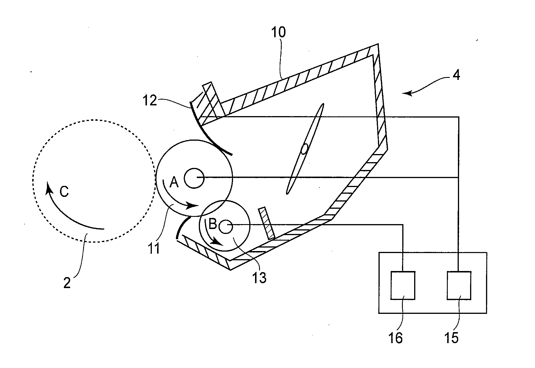
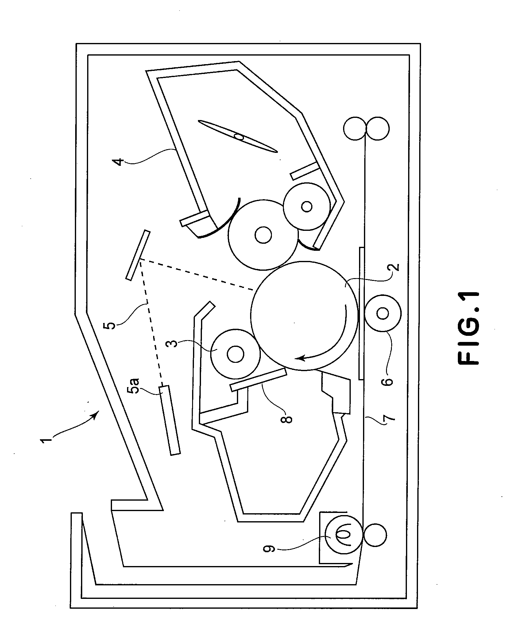
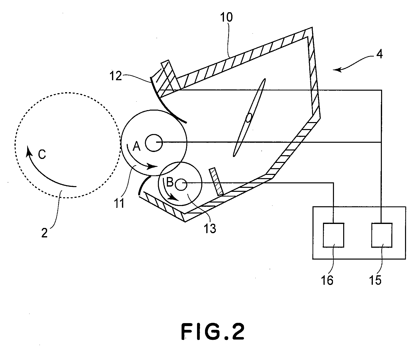
[0023]FIG. 1 is a schematic sectional view of the image forming apparatus in accordance with the present invention, and FIG. 2 is a schematic sectional view of the developing apparatus employed by the image forming apparatus.

[0024]First, referring to FIG. 1, the general structure and operation of the image forming apparatus 1 structured in accordance with the present invention will be described.

[0025]The image forming apparatus 1 in this embodiment is a laser beam printer which forms an image on a sheet of transfer medium (recording paper, OHP sheet, fabric, etc.) with the use of an electrophotographic image forming method, and outputs the sheet of transfer medium. More specifically, it forms an image on the recording medium, in response to picture information signals from a picture information source, such as a personal com...

embodiment 2

[0045]Next, referring to FIG. 3, the developing apparatus employed by an image forming apparatus, in another preferred embodiment of the present invention will be described. The basic structure and operation of the developing apparatus and image forming apparatus in this embodiment are roughly the same as those in the first preferred embodiment. Therefore, an element of the apparatuses in this embodiment, which is practically the same in function and structure as, or equivalent in function and structure to, the one in the first embodiment is given the same referential symbol as the one given to describe the first embodiment, and will not be described in detail. This embodiment is different from the first embodiment in that a roller, the arithmetic average roughness Ra (JIS B 0601-1994) of which satisfies the following mathematical expression, in which Ra [μm] and X [μm] stand for the average roughness Ra of the development roller 11 and the volume average particle diameter of the de...

experiment 1

[Experiment 1]

[0060]In light of the results in the first to third comparative embodiments, it was thought to scrape away the fog formation toner by setting the ratio of the peripheral velocity of the development drum 11 relative to that of the photosensitive drum 2 to 120% at which frictional force works between the development roller 11 and photosensitive drum 2, and increasing the amount by which toner is coated on the development roller 11 while being controlled by the regulation blade 12 in order to deal with the fog problem and to achieve a satisfactory level of “solid black density”.

[0061]In this experiment, the toner was 6 μm in volume average particle diameter, and the ratio of the peripheral velocity of the development roller 11 relative to that of the photosensitive drum 2 was 120%. FIG. 6 is a graph showing the relationships among the average roughness Ra of the development roller 11, which was varied in a range of 0.1 μm-3.5 μm, the amount of the fog generation toner on ...


PUM


Abstract

An image forming apparatus includes an image bearing member; a developer carrying member, contactable to the image bearing member, for carrying a developer to a developing position to develop an electrostatic image formed on the image bearing member with the developer; a supplying member for supplying the developer to the developer carrying member, wherein a peripheral speed of the developer carrying member is not less than 1.05 times and not more than 1.20 times a peripheral speed of the image bearing member, and an arithmetic average roughness Ra is not less than 0.20 times and not more than 0.33 times a volume average particle size of the developer, wherein a potential applied to the supplying member is different from a potential applied to the developer carrying member toward a larger potential of a regular charge polarity of the developer.

Description

FIELD OF THE INVENTION AND RELATED ART[0001]The present invention relates to an image forming apparatus using an electrophotographic type or electrostatic recording type process, such as a laser beam printer, a copying machine or a facsimile machine.[0002]Conventionally, for example, in an image forming apparatus using the electrophotographic type process, a surface of an electrophotographic photosensitive member (photosensitive member) (image bearing member) is charged by a charging means, and thereafter, the surface of the photosensitive member is exposed with light modulated in accordance with image information, so that electrostatic image (latent image) is formed on the surface of the photosensitive member. The electrostatic image is developed with toner of a developer supplied from a developing device into a toner image. The toner image is transferred from the photosensitive member onto a transfer material (printing sheet, OHP sheet, textile or the like), and then, the toner im...

Claims


Application Information

Patent Timeline
Patent Type & Authority Applications(United States)
IPC IPC(8): G03G15/08
CPCG03G2215/0634G03G15/065
Inventor ENDO, RIEMORIYA, SHUJISAKAIZAWA, KATSUHIROTAKAHASHI, NORIO
Owner CANON KK
Learn More