Ultra-wide-span roller guide rail structure

A technology of roller guide rail and span, applied in the direction of bearings, linear motion bearings, bearing components, etc., can solve the problems of large support table, affecting the installation and use of equipment, etc., to improve the use capacity, ensure normal use, and reduce self-load Effect

Pending Publication Date: 2021-01-29
中山市智合数控科技有限公司
View PDF0 Cites 0 Cited by
  • Summary
  • Abstract
  • Description
  • Claims
  • Application Information

AI Technical Summary

Problems solved by technology

[0004] The purpose of the present invention is to provide an ultra-wide-span roller guide rail structure in order to solve the problem that the support of the ultra-wide-span guide rail relies heavily on the integral support platform, which affects the installation and use of the equipment

Method used


Image

  • Ultra-wide-span roller guide rail structure
  • Ultra-wide-span roller guide rail structure
  • Ultra-wide-span roller guide rail structure

Examples


Embodiment 1

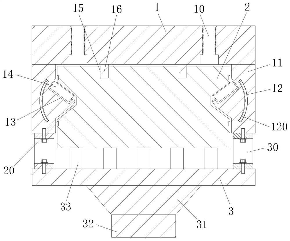
[0027] Example 1, please refer to Figure 1~3 , an ultra-wide-span roller guide rail structure, comprising a sliding body 1, a rail body 2 supporting the sliding body 1, and a fixing frame 3 stably supporting the rail body 2;

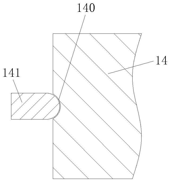
[0028] The sliding body 1 includes a rectangular parallelepiped fixed platform directly above the guide rail body 2, a side plate 11 and a sliding assembly. The side plate 11 is located on the left and right sides of the fixed platform and is integrally formed with the fixed platform. The top of the fixed platform is preset. There is a threaded mounting hole 10, and the upper bottom of the fixed platform is integrally formed with a fitting strip 16; the middle position of the side plate 11 is preset with a through groove 12; the sliding assembly includes a roller 14, and the inner position of the side plate 11 is A sinking groove 13 is preset, and the roller 14 is placed in the sinking groove 13;

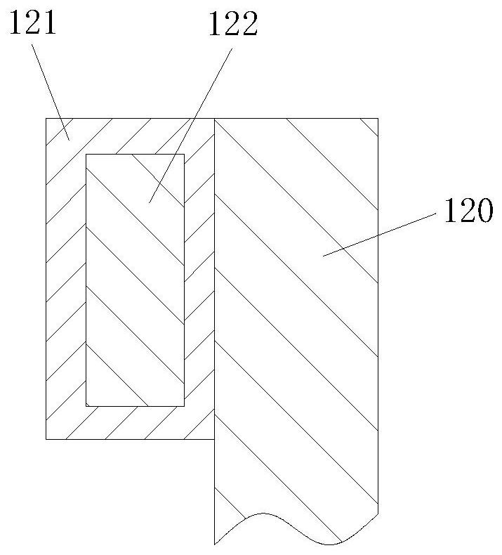
[0029] A dust-proof curtain 120 is worn in the through...

Embodiment 2

[0033] Example 2, please refer to Figure 1~5 , an ultra-wide-span roller guide rail structure, comprising a sliding body 1, a rail body 2 supporting the sliding body 1, and a fixing frame 3 stably supporting the rail body 2;

[0034] The sliding body 1 includes a rectangular parallelepiped fixed platform directly above the guide rail body 2, a side plate 11 and a sliding assembly. The side plate 11 is located on the left and right sides of the fixed platform and is integrally formed with the fixed platform. The top of the fixed platform is preset. There is a threaded mounting hole 10, and the upper bottom of the fixed platform is integrally formed with a fitting strip 16; the middle position of the side plate 11 is preset with a through groove 12; the sliding assembly includes a roller 14, and the inner position of the side plate 11 is A sinking groove 13 is preset, and the roller 14 is placed in the sinking groove 13;

[0035] A dust-proof curtain 120 is worn in the through...


PUM


Abstract

The invention discloses an ultra-wide-span roller guide rail structure. The ultra-wide-span roller guide rail structure comprises a guide rail body, wherein a sliding body is installed on the guide rail body; a fixing frame is installed at the bottom of the guide rail body; side plates are integrally formed and fixed on the left side and the right side of the sliding body; sinking grooves are pre-formed in the inner sides of the side plates; rollers are installed in the sinking grooves; arc-shaped grooves are pre-formed in the centers of the left ends and the right ends of the rollers; convexcolumns with hemispherical end parts are arranged in the arc-shaped grooves in an abutting mode; the convex columns are welded and fixed at corresponding positions in the sinking grooves; rolling grooves are pre-formed in the left side and the right side of the guide rail body; and the rollers abut against the rolling grooves. According to the ultra-wide-span roller guide rail structure, a stressframe is composed of two hollow triangular blocks which are arranged in a forward and reverse mode, on the physical basis that a triangular structure is matched and has stability, the overall weight of the stress frame is reduced while the structural stability is ensured through hollowing, so that the load of a supporting structure of the guide rail body is reduced, the effective load capacity ofthe guide rail can be improved, and the use capacity is improved.

Description

technical field [0001] The invention belongs to the technical field of guide rail equipment, in particular to an ultra-wide-span roller guide rail structure. Background technique [0002] There are generally two types of linear guides widely used at present, one is rolling type and the other is sliding type. Rolling linear guide is a kind of rolling guide, which uses steel balls or rollers to perform infinite rolling between the slider and the slide rail. Circulation, so that the load platform can easily move linearly along the slide rail with high precision, and its friction coefficient can be reduced to 1 / 50 of that of the traditional slide guide, so that it can easily achieve the positioning accuracy of μm level. [0003] Among them, under the condition of ultra-wide span, the guide rail needs to meet the needs of traditional rolling guidance, and at the same time, it needs to take into account the problem of support rigidity. The traditional support problem mostly relies...

Claims


Application Information

Patent Timeline
Patent Type & Authority Applications(China)
IPC IPC(8): F16C29/04F16C29/08F16C33/78
CPCF16C29/004F16C29/04F16C29/084F16C33/782
Inventor 王江伟黄祖寅刘晓邦
Owner 中山市智合数控科技有限公司
Why Eureka
Try Eureka