Discharging electrode and light catalyst reactor

一种光催化剂、放电电极的技术,应用在光催化剂反应装置领域,能够解决不能稳定照射放电光、破损、电极变形等问题,达到高物质分解性能、耐腐蚀性提高、提高处理效率的效果

Inactive Publication Date: 2002-12-25
KK TOSHIBA
View PDF0 Cites 16 Cited by
  • Summary
  • Abstract
  • Description
  • Claims
  • Application Information

AI Technical Summary

Problems solved by technology

However, depending on the installation method or the state of harmful substances that flow in, for example, when the flow rate is very fast or there is a lot of dust, there may be deviations in the installation location, deformation, damage, etc. of the electrodes, and it may not be possible to stably irradiate the discharge light on the photocatalyst.

Method used


Image

  • Discharging electrode and light catalyst reactor
  • Discharging electrode and light catalyst reactor
  • Discharging electrode and light catalyst reactor

Examples


no. 1 Embodiment approach

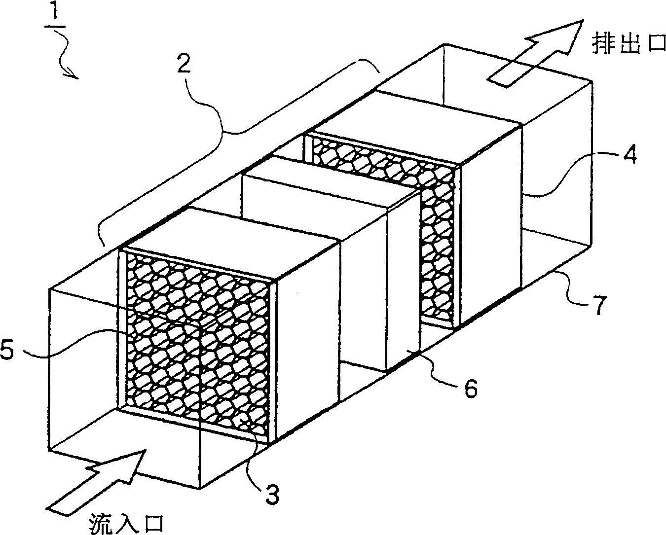
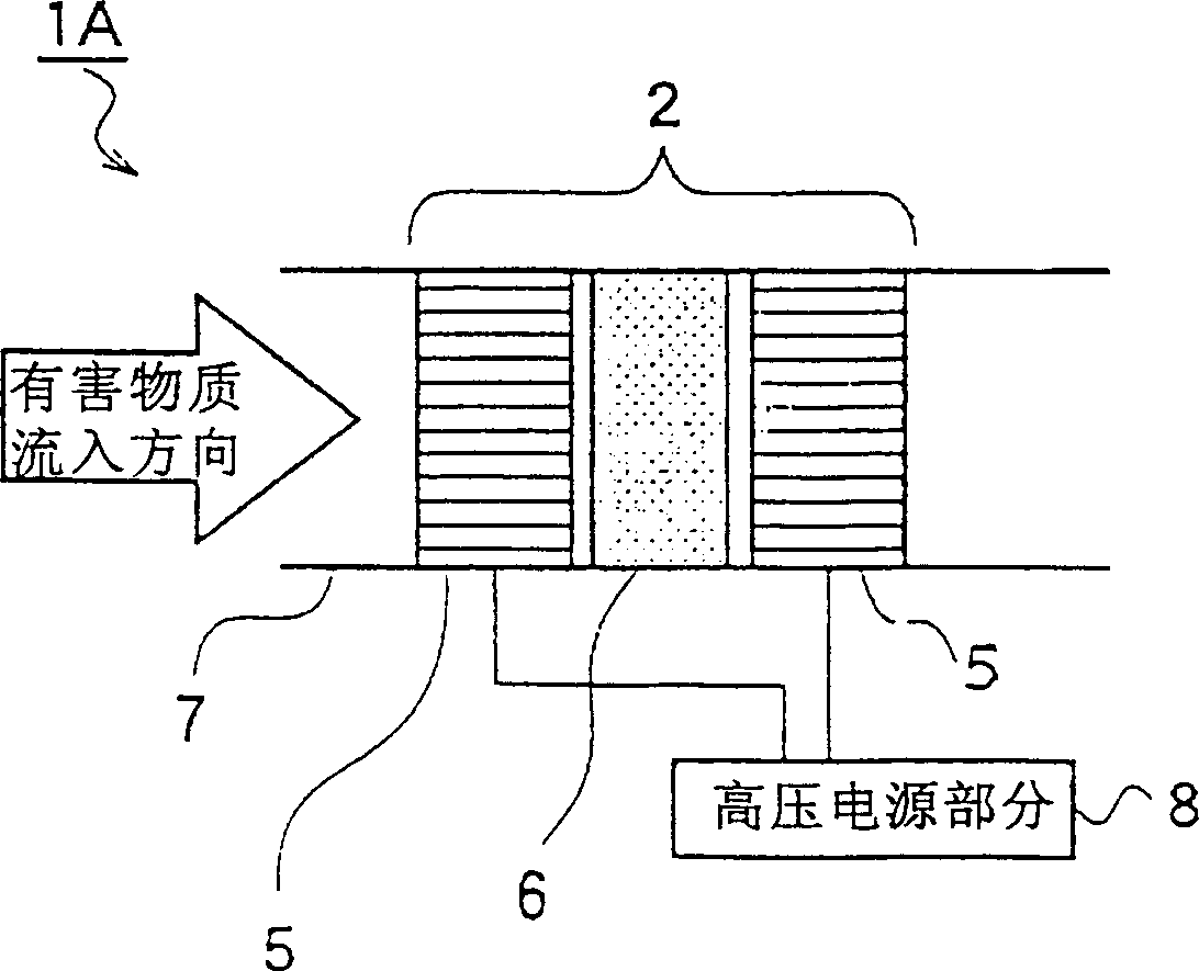
[0046] first according to figure 1 and figure 2 The minimum constituent unit of the photocatalyst reaction device of the present invention will be described. figure 2 yes figure 1 Schematic diagram of the photocatalyst reaction device.

[0047] figure 1 The photocatalyst reaction device 1 in figure 2 Among them, the photocatalyst reaction device 1A) is composed of a unit structure and its housing case 7 . The casing 7 has a cylindrical structure, has an inlet and an outlet, and allows the gas containing harmful substances to pass through. The unit structure 2 is composed of a pair of honeycomb electrodes 5 and a photocatalyst assembly 6 sandwiched therebetween. A pair of honeycomb electrodes 5 and the unshown high-voltage power supply part ( figure 2 In, the high-voltage power supply part 8) is connected.

[0048] The honeycomb electrode 5 is a three-dimensional electrode, which is formed into a honeycomb shape with a conductive film. It is composed of a honeyco...

no. 2 Embodiment approach

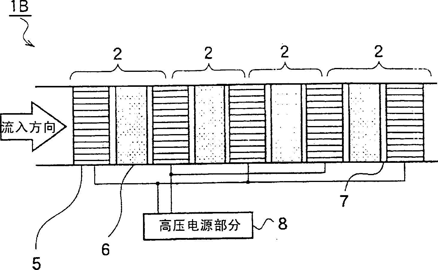
[0077] image 3 for will be in figure 1 ( figure 2 ) shows a case where the unit structure 2 is made into a plurality of stacked layers.

[0078] image 3 The photocatalyst reaction device 1B is composed of four unit structures 2 and their storage cases 7 and a high-voltage power supply part 8 . The unit structure body 2 is composed of a pair of honeycomb electrodes 5 and a photocatalyst assembly 6 sandwiched therebetween. The honeycomb electrodes 5 are respectively connected to high voltage power supply parts 8 .

[0079] In the present embodiment, by arranging four unit structures 2, adjacent electrodes are shared among the unit structures 2. FIG. By arranging the electrodes alternately so that both sides of the electrodes emit light, discharge light can be efficiently obtained.

[0080] Because the composition and structure of the honeycomb electrode 5 and the material used for the electrode, the structure of the photocatalyst module 6 and the material of the semico...

no. 3 Embodiment approach

[0085] Figure 4 is in figure 1 ( figure 2 ) on the photocatalyst reaction device 1 (1A) has increased the situation of the ozonolysis catalyst 9.

[0086] Figure 4 The photocatalyst reaction device 1C is composed of a housing unit structure 2 , a housing 7 for an ozonolysis catalyst 9 , and a high-voltage power supply 8 .

[0087]The unit structure 2 is composed of a pair of honeycomb electrodes 5 connected to a high-voltage power supply section 8 and a photocatalyst assembly 6 sandwiched therebetween. In addition, the ozonolysis catalyst 9 is located on the downstream side of the unit structure 2 with respect to the gas inflow direction.

[0088] Because the composition and structure of the honeycomb electrode 5 and the material used for the electrode, the structure of the photocatalyst module 6 and the material of the semiconductor particles used in the module, and the high-voltage power supply part 8 are the same as those of the first embodiment, so the description ...


PUM

PropertyMeasurementUnit
coating thicknessaaaaaaaaaa
wavelengthaaaaaaaaaa

Abstract

The present invention provides a discharge electrode and a photocatalyst reaction device, which utilizes a three-dimensional discharge electrode that discharges effectively and stably, the relationship between the discharge light emitted from the discharge electrode and the photocatalyst, and can effectively, long-term, and stably remove harmful substances. The discharge electrode is a three-dimensional electrode. The main body (3) of the honeycomb electrode is formed of a conductive film. The shape is honeycomb when viewed from the front and back. Gases containing harmful substances can pass from the front to the back. The sides of the electrode are conductive. The casing (4) covers the electrode and has a specified thickness in the direction from the front to the back of the electrode. In addition, the photocatalyst reaction device includes at least one group of unit structures (2). The unit structure (2) has: at least one photocatalyst component (6) and a honeycomb electrode (5), wherein the photocatalyst component (6) ) holds a photocatalyst on its ceramic substrate with a three-dimensional network structure; among a pair of electrodes sandwiching the photocatalyst component 6 between the honeycomb electrode (5), at least one electrode is composed of a conductive shell (4) and It is composed of honeycomb electrode body 3.

Description

technical field [0001] The present invention relates to a photocatalyst reaction device, which can effectively and stably remove harmful substances by using a three-dimensional discharge electrode capable of effectively and stably discharging and the relationship between the discharge light (ultraviolet rays) emitted from the electrode and the photocatalyst. technical background [0002] Dioxins and NO contained in the atmosphere x It is a well-known fact that environmental pollution caused by harmful substances such as pollutants and harmful substances in sewage has become a social problem. Research and development of methods for effectively removing these harmful substances are actively being carried out. In addition, in recent years, ethylene gas as an anti-corrosion gas in refrigerators; formaldehyde, toluene, xylene, and p-dichlorobenzene, which are known as the cause of housing syndrome; Hazardous substances have become a subject for research. [0003] Conventionall...

Claims


Application Information

Patent Timeline
Patent Type & Authority Applications(China)
IPC IPC(8): A61L9/00A61L9/20B01D53/32B01D53/86B01D53/88B01J19/00B01J19/08B01J35/00B01J35/02B01J35/04B03C3/016B03C3/41
CPCB01D53/32B01D53/885B01D2255/802B01D2257/106B03C3/016B03C3/41Y02C20/10B01J35/56B01J35/39B01D53/86
Inventor 濑川昇内田裕今村武志村尚彦
Owner KK TOSHIBA
Why Eureka
Try Eureka