Low pressure egr apparatus

a low-pressure egr and apparatus technology, applied in mechanical apparatus, operating means/release devices of valves, machines/engines, etc., can solve the problems of not being able to meet the requirements of low-pressure egr apparatus, difficult for low-pressure egr apparatus b>1/b> to re-circulate large, and not being able to achieve such low-density egr gas density

Active Publication Date: 2010-08-19
DENSO CORP
View PDF14 Cites 41 Cited by
  • Summary
  • Abstract
  • Description
  • Claims
  • Application Information

AI Technical Summary

Benefits of technology

[0029]Accordingly, it becomes possible to suppress an increase of the cost for the LP EGR apparatus and to realize a small-sized and light-weight EGR apparatus.

Problems solved by technology

It is, however, not possible to achieve such low density of EGR gas with the high pressure EGR apparatus 31.
On the other hand, it is difficult for the low pressure EGR apparatus 1 to re-circulate large amount of the EGR gas into the engine 2.
In other words, the low pressure EGR apparatus 1 can not meet a requirement for re-circulating the large amount of the EGR gas into the engine 2, even when there is such requirement in an engine operating condition.
It is, therefore, necessary to provide not only an actuator J1 for driving the low pressure EGR control valve 5 but also another actuator J2 for driving the intake-air valve 6, which would cause increases in cost, in size, and in weight of the EGR apparatus.
It is not possible to obtain valve operating characteristics required for the respective valves.

Method used


Image

  • Low pressure egr apparatus
  • Low pressure egr apparatus
  • Low pressure egr apparatus

Examples


second embodiment

[0132]A second embodiment of the invention will be explained with reference to FIGS. 8A to 8D and FIG. 9. In the drawing, the same reference numerals are used to the same or similar components and / or portions of the first embodiment.

[0133]The second embodiment relates to a modification of the control program carried out by the ECU. More exactly, the second embodiment relates to the control program for the operating mode of high EGR density, in which the larger amount of the EGR gas is re-circulated into the engine 2 via the L-P EGR apparatus 1.

[0134]According to the control program for high-pressure and / or low-pressure EGR amount, the EGR amount is controlled depending on the opening degree of the intake-air valve 6 from its maximum valve opening position (to the valve closing direction) as well as the opening degree of the L-P EGR control valve 5 from its maximum valve closing position (to the valve opening direction).

[0135]An example will be explained with reference to FIGS. 8A to...

third embodiment

[0156]A third embodiment will be explained with reference to FIGS. 10A to 10C.

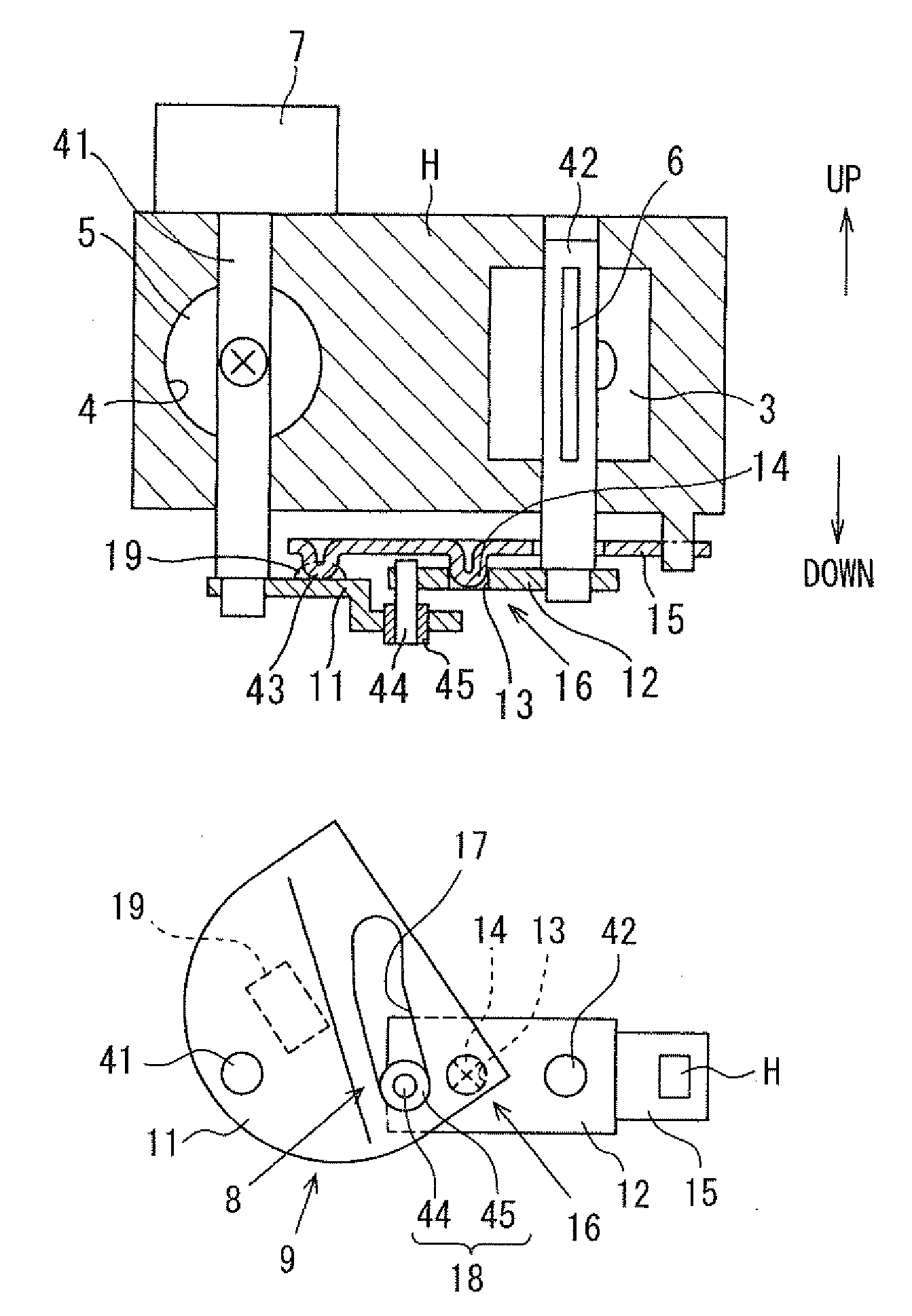
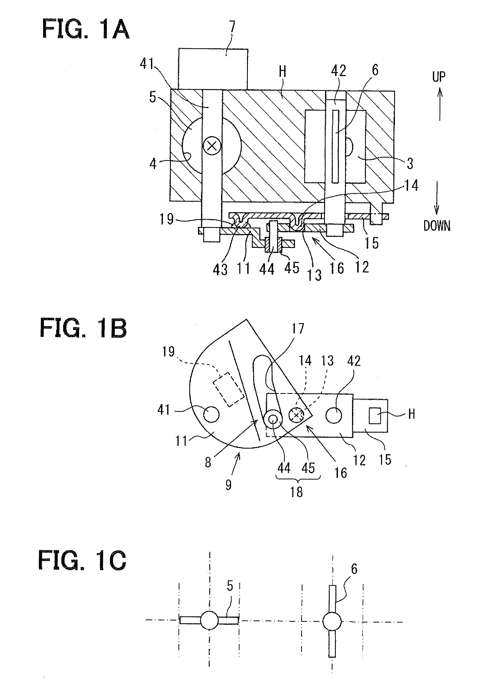
[0157]FIG. 10A corresponds to FIG. 1A and a portion encircled in FIG. 10A is shown in FIG. 102 in an enlarged scale. As already explained, the sliding end portion 43 is integrally formed with the lever 15 according to the first embodiment. More exactly, the sliding end portion 43 is formed at the forward end of the lever 15 in such a way that it is formed in a hemispherical protrusion protruding in the downward direction toward the cam plate 11.

[0158]According to the third embodiment, as shown in FIG. 10C, a ball 46 is used as the sliding end portion 43. More exactly, a hemispherical projection 47 is formed at the forward end of the lever 15, which is projected in the upward direction (in the direction opposite to the cam plate 11), and the ball 46 is rotatably arranged in an inside of the projection 47 so that the ball 46 forms the sliding end portion 43.

[0159]As a result, contact resistance between the c...

fourth embodiment

[0160]A fourth embodiment of the invention will be explained with reference to FIG. 11.

[0161]According to the first embodiment, the lock pin 14 is integrally formed in the lever 15. More exactly, the lock pin 14 is formed at the intermediate portion of the lever 15 in a semi-spherical shape in such a way that the part of the spring material for the lever 15 is downwardly protruded (to a side of the cam plate).

[0162]According to the fourth embodiment, the lock pin 14 is made as a separate member and fixed to the lever 15.


PUM


Abstract

A converting mechanism is provided between an EGR control valve driven by an actuator and an intake-air valve for generating negative pressure, so that the intake-air valve is also driven by the actuator. The converting mechanism has a cam plate rotated together with the EGR control valve and an arm rotated together with the intake-air valve. A cam groove formed in the cam plate is engaged with a driving pin of the arm. The intake-air valve is held at its maximum valve opening position, when the EGR control valve is rotated in a first angular range, while the intake-air valve is rotated from the valve opening position to a maximum valve closing position when the EGR control valve is rotated in a second angular range.

Description

CROSS REFERENCE TO RELATED APPLICATION[0001]This application is based on Japanese Patent Application No. 2009-035178 filed on Feb. 18, 2009, the disclosure of which is incorporated herein by reference.FIELD OF THE INVENTION[0002]The present invention relates to a low pressure EGR apparatus for re-circulating a part of exhaust gas discharged from an engine (an internal combustion engine for producing driving power by combusting fuel) into a low negative pressure portion of an intake-air passage (for example, an upstream side of a throttle valve, at which small negative pressure is generated).BACKGROUND OF THE INVENTION[0003]A prior art of the present invention will be explained with reference to FIGS. 13 and 14. Reference numerals used in FIGS. 13 and 14 correspond to those used for explaining embodiments of the present invention.[0004]A high pressure EGR apparatus 31 is known in the art as a technology for suppressing generation of nitrogen oxides (NOx) contained in exhaust gas of a...

Claims


Application Information

Patent Timeline
Patent Type & Authority Applications(United States)
IPC IPC(8): F02M25/07F16K31/44
CPCF02B29/0406F02M25/0707F02M25/0709F02M25/0724Y02T10/121F02M25/0732F02M25/0786F02M25/0793F16K35/14F02M25/0728F02M26/05F02M26/06F02M26/21F02M26/25F02M26/24F02M26/64F02M26/70F02M26/10
Inventor FURUKAWA, AKIRASHIMANE, OSAMUMIYAZAKI, SHINSUKEMORITANI, YUICHIRO
Owner DENSO CORP
Why Eureka
Try Eureka