
Liquid ejecting apparatus and liquid ejecting method

a liquid ejecting apparatus and liquid ejecting technology, which is applied in the direction of printing, other printing apparatus, etc., can solve the problems of inadequate study of replenishment properties and poor ejecting of liquid in the nozzle, and achieve the effect of suppressing poor ejecting

Active Publication Date: 2010-08-19
SEIKO EPSON CORP
View PDF6 Cites 2 Cited by
  • Summary
  • Abstract
  • Description
  • Claims
  • Application Information

AI Technical Summary

Benefits of technology

[0006]An advantage of some aspects of the invention is that it effectively suppresses poor ejection due to lack of replenishment of liquid in a case where liquid is continuously ejected from a nozzle.

Problems solved by technology

In a liquid ejecting apparatus such as an ink jet printer, there was a problem that in a case where the replenishment amount of liquid which is replenished from a liquid replenishment section is smaller than the ejection amount of liquid which is ejected from a nozzle, poor ejection of liquid occurs in the nozzle.
However, in the prior apparatus, the relationship between time series change in the ejection amount in a case where liquid is continuously ejected from a nozzle and a replenishment property was not sufficiently studied.

Method used


Image

  • Liquid ejecting apparatus and liquid ejecting method
  • Liquid ejecting apparatus and liquid ejecting method
  • Liquid ejecting apparatus and liquid ejecting method

Examples


first embodiment

Concerning the Printing System

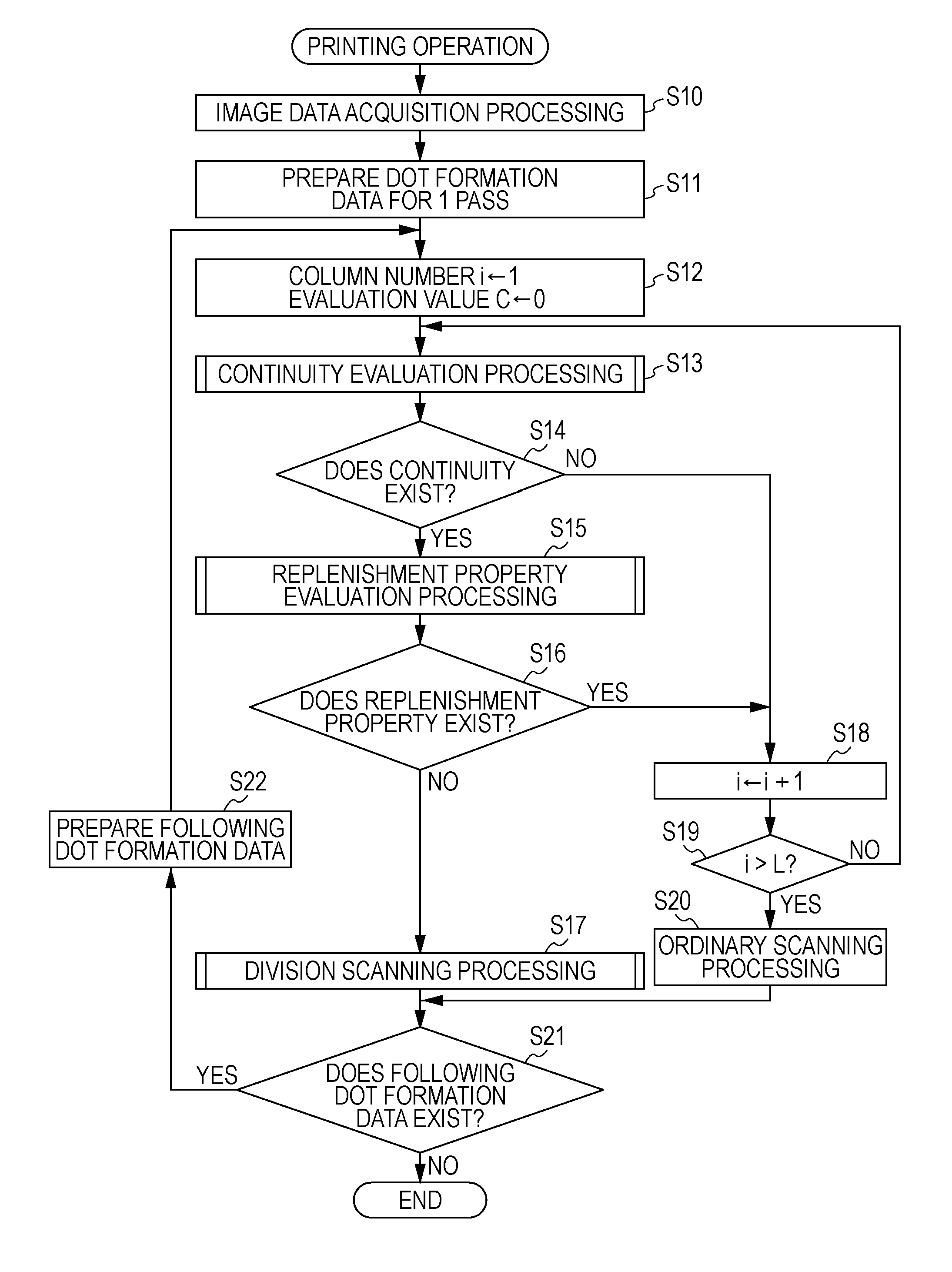
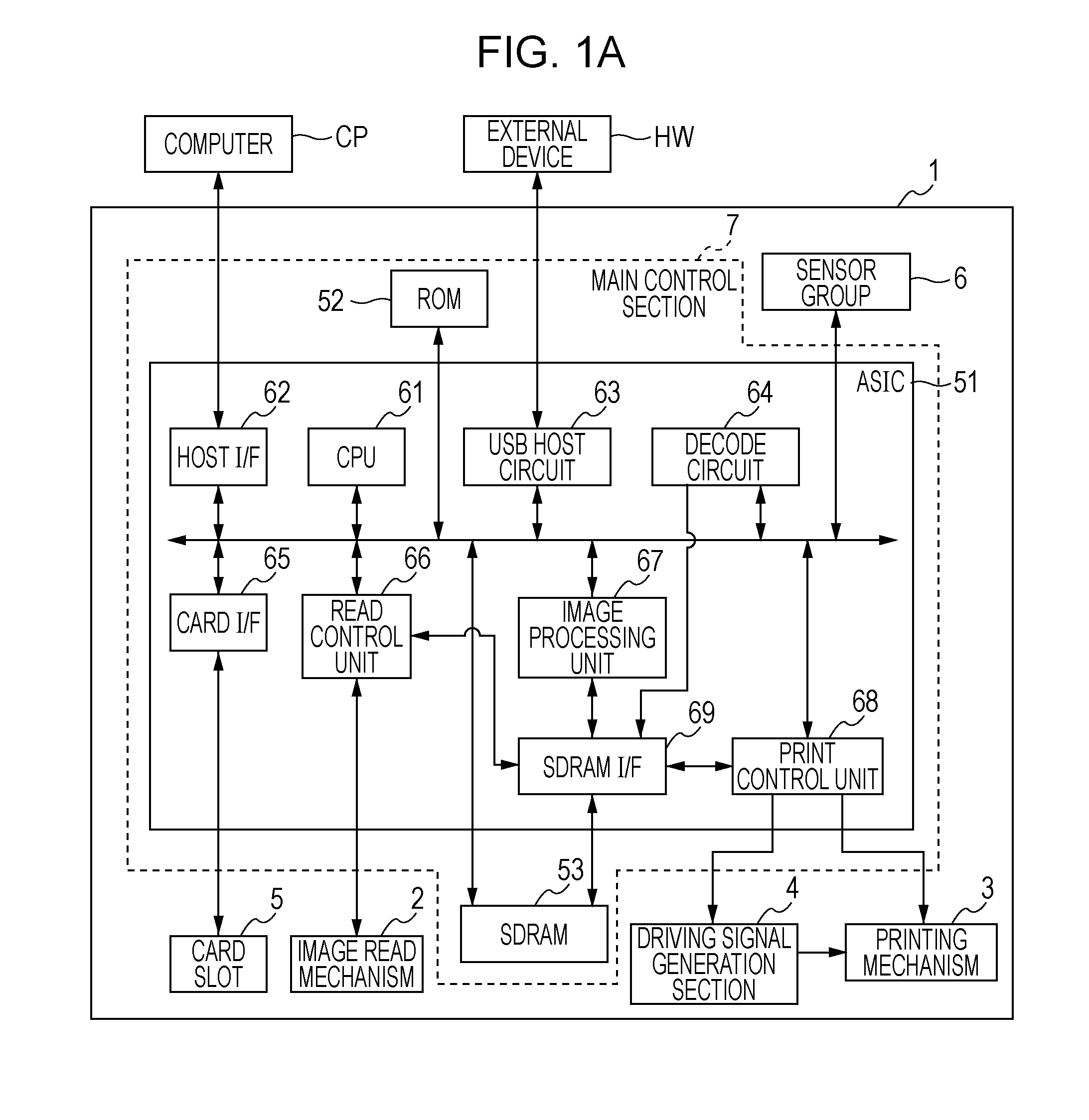
[0042]A printing system illustrated in FIG. 1A is for printing an image on a paper S (refers to FIG. 2, etc.) and includes a computer CP and a multifunction device 1. The multifunction device 1 is an apparatus which also acts as an ink jet printer, and is one kind of liquid ejecting apparatus which prints an image on a medium such as the paper S by ejecting ink (aqueous ink or oily ink) in the form of liquid. The computer CP carries out control for making the multifunction device 1 perform liquid ejection operation.

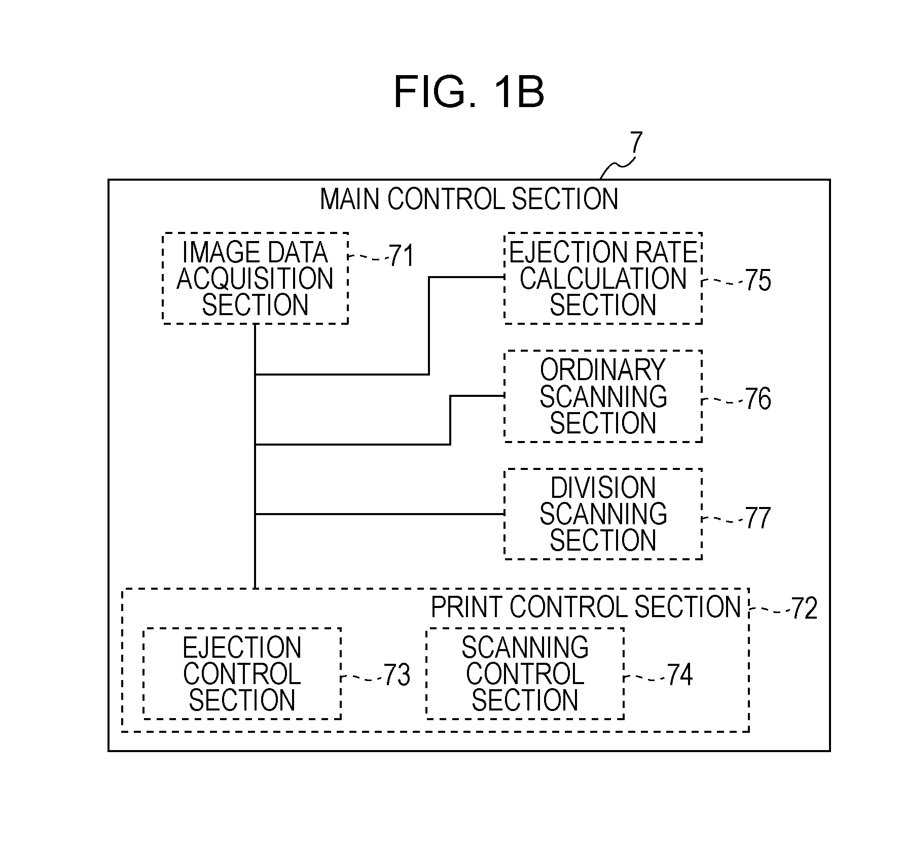
[0043]The multifunction device 1 has an image read mechanism 2, a printing mechanism 3, a driving signal generation section 4, a card slot 5, a sensor group 6, and a main control section 7. In the multifunction device 1, the controlled objects, that is, the image read mechanism 2, the printing mechanism 3, and the driving signal generation section 4 are controlled by the main control section 7 which serves as a controller.

[0044]The image read...


PUM


Abstract

A liquid ejecting apparatus includes a liquid ejecting head that ejects liquid from a nozzle. A head movement section moves the liquid ejecting head in a movement direction. A controller controls a movement ejection operation that ejects the liquid from the nozzle while moving the liquid ejecting head in the movement direction. If there is satisfied a decision condition that indicates that the ejection rate is excessive, the controller causes the number movement ejection operations related to a certain range to be larger than if the decision condition were not satisfied. With respect to second liquid being higher in viscosity than first liquid, the controller determines the number movement ejection operations related to the above-mentioned certain range by the above-mentioned decision condition determined as excess of the above-mentioned ejection rate at an ejection rate being smaller than that of the first liquid.

Description

BACKGROUND[0001]1. Technical Field[0002]The present invention relates to a liquid ejecting apparatus and a liquid ejecting method.[0003]2. Related Art[0004]In a liquid ejecting apparatus such as an ink jet printer, there was a problem that in a case where the replenishment amount of liquid which is replenished from a liquid replenishment section is smaller than the ejection amount of liquid which is ejected from a nozzle, poor ejection of liquid occurs in the nozzle. With respect to such a problem, there has been proposed an apparatus which controls dot formation on the basis of a temperature of a liquid ejecting head (refers to JP-A-2004-66550).[0005]However, in the prior apparatus, the relationship between time series change in the ejection amount in a case where liquid is continuously ejected from a nozzle and a replenishment property was not sufficiently studied.SUMMARY[0006]An advantage of some aspects of the invention is that it effectively suppresses poor ejection due to lack...

Claims


Application Information

Patent Timeline
IPC IPC(8): B41J29/38
CPCB41J2/2132B41J2/175
Inventor ISHIKAWA, HIROYUKI
Owner SEIKO EPSON CORP
Learn More