
Electric steering lock for vehicle

a technology of electric steering lock and steering lock, which is applied in the direction of shafts, mechanical control devices, restricting/preventing/returning movement of parts, etc., can solve the problems of over-scale of electric motors, long response time in the release phase, and generating overloads on transmission and drive motors of transmissions, etc., to achieve simple and economical effects

Inactive Publication Date: 2010-08-26
TRW AUTOMOTIVE ITAL
View PDF20 Cites 19 Cited by
  • Summary
  • Abstract
  • Description
  • Claims
  • Application Information

AI Technical Summary

Benefits of technology

[0006]The purpose of the present invention is to implement an electric steering lock whose construction characteristics provide a simple, economical solution to the aforementioned problems.

Problems solved by technology

When the prong engages the housing, following accidental or involuntary rotation of the steering shaft, in some cases transverse shear stress is applied to the elongated element which inevitably generates friction components between the prong and the attachment housing and also between the element and the related guide.
These friction components oppose return of the element to its retracted resting position, generating overloads on the transmission and the drive motor of the transmission with, consequently, much longer response times in the release phase than envisaged in the project.
To take into account the above problem, the electric motors used are often over-scaled with evident increases in the related construction costs.

Method used


Image

  • Electric steering lock for vehicle
  • Electric steering lock for vehicle
  • Electric steering lock for vehicle

Examples


Embodiment Construction

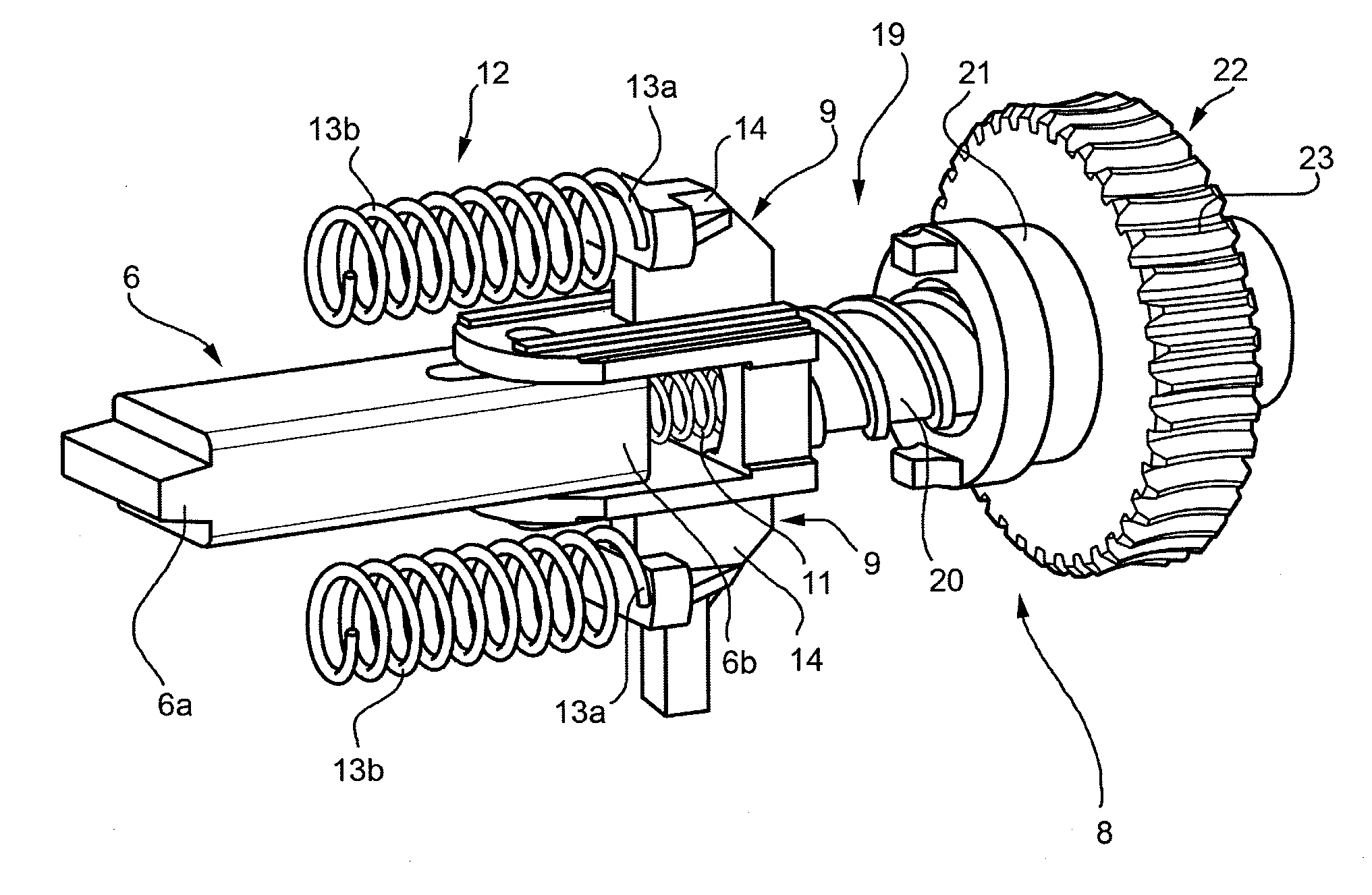
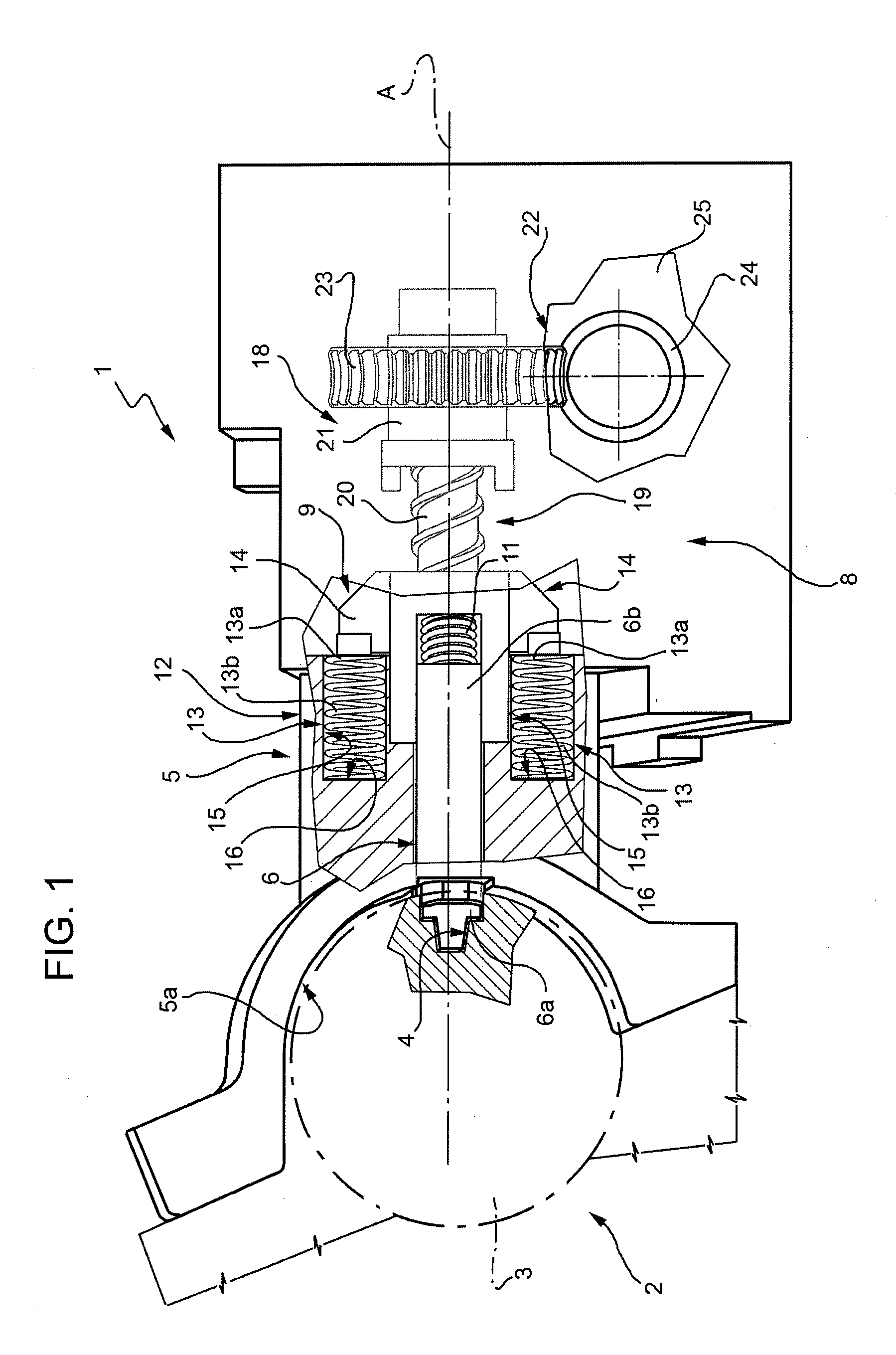
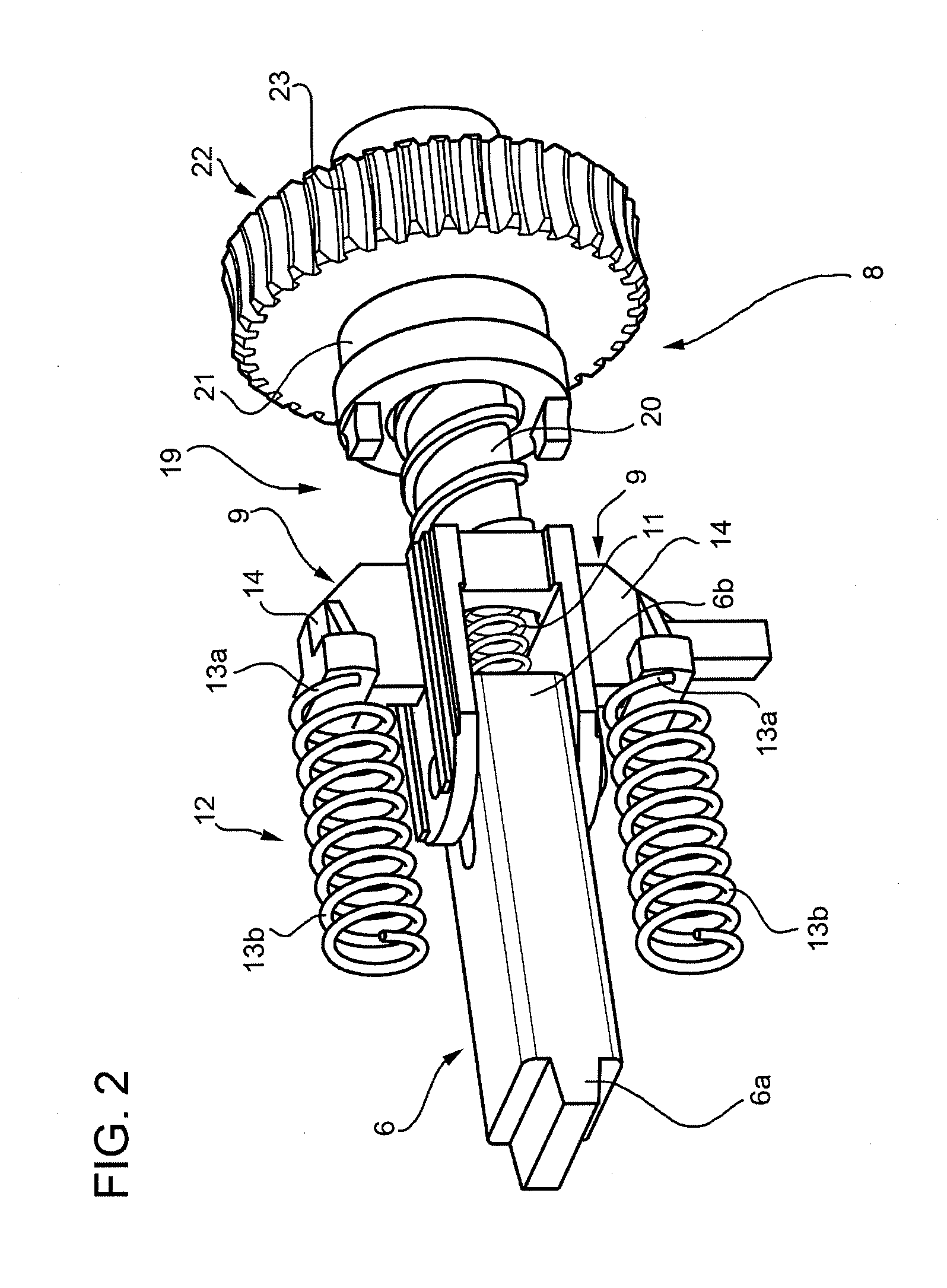
[0012]In FIG. 1, 1 indicates, generally, an electric steering lock for vehicles coupled to a known steering group 2, whose steering shaft 3 has a radial housing 4 (FIG. 2).

[0013]The electric steering lock 1 comprises an outer fixed attachment housing 5, which defines a seat 5a (FIG. 1) in which the shaft 3 is housed in known manner, and houses an elongated angular locking element 6 of the shaft 3 in relation to the outer housing 5. The element 6 is coupled to the housing 5 in such a way as to slide axially in a rectilinear direction A (FIG. 1) perpendicular to the shaft 3 and moves, by virtue of the thrust exerted by a driving group 8, between a forward angular locking position in which a front portion or prong of the element 6 protrudes inside the seat 5a and engages the radial housing 4 (FIG. 1), and a retracted resting position in which the front portion 6a disengages the housing 4 allowing the shaft 3 to rotate freely in relation to the housing 5.

[0014]As shown in FIG. 1 and, in...


PUM


Abstract

In an electric steering lock for vehicles, an element for angular locking of a steering shaft is displaced by a driving group between a forward operational position, in which it holds the steering shaft in an angular position, and a retracted resting position in which it allows a free rotation of the steering shaft; the driving group being provided with an electric motor and a mechanical transmission interposed between the motor and the locking element, and with an elastic device cooperating with the electric motor to displace the locking element towards its retracted resting position.

Description

[0001]The present invention relates to an electric steering lock for vehicles.[0002]In particular, the present invention relates to an electric steering lock for vehicles comprising an elongated locking element and a power mechanical transmission to displace the elongated element between a forward operational position in which the elongated element holds the steering shaft of the vehicle in a fixed angular position in relation to a fixed reference element, and a retracted resting or disengaged position in which the elongated element permits free rotation of the steering shaft in relation to such fixed element.BACKGROUND OF THE INVENTION[0003]The elongated element slides in a guide and has a front terminal portion or prong which, when the elongated element is in the forward operational angular blocking position, engages in a radial housing of the shaft.[0004]When the prong engages the housing, following accidental or involuntary rotation of the steering shaft, in some cases transvers...

Claims


Application Information

Patent Timeline
Patent Type & Authority Applications(United States)
IPC IPC(8): B60R25/02E05B47/00B60R25/0215
CPCB60R25/02153Y10T70/565
Inventor GRAGLIA, DANIELE
Owner TRW AUTOMOTIVE ITAL
Learn More