Back cover and method of assembling back cover

a back cover and assembling technology, applied in the field of back cover and assembling back cover, can solve the problems of poor light source illumination circuit, reduced waterproofness, and gap between the mounting portion the outer circumferential surface of the heat dissipating member, so as to improve the waterproofness of the lamp chamber and improve the mounting strength of the case member

Inactive Publication Date: 2010-08-26
KOITO MFG CO LTD
View PDF5 Cites 4 Cited by
  • Summary
  • Abstract
  • Description
  • Claims
  • Application Information

AI Technical Summary

Benefits of technology

[0008]One or more embodiments of the present invention provide a back cover and a back cover assembling method in which mounting strength of a case member to a case main body is improved and waterproofness of a lamp chamber is also improved.

Problems solved by technology

However, in the back cover described in JP-A-2008-277008, since the heat dissipating member (the case member) is mounted on the cover main body by being fitted in the heat dissipating member mounting portion and being bonded therein, there is a fear that a gap is produced between an inner circumferential surface of the heat dissipating member mounting portion and an outer circumferential surface of the heat dissipating member.
When such a gap is produced, there is caused such a drawback that a light source illumination circuit is badly affected or that a front cover is clouded up by water which infiltrates a lamp chamber whose waterproofness is reduced.
In addition, there is caused such a drawback that the mounting strength with which the case member is mounted on the cover main body is reduced to thereby produce looseness or that the heat dissipating member falls from the cover main body.

Method used


Image

  • Back cover and method of assembling back cover
  • Back cover and method of assembling back cover
  • Back cover and method of assembling back cover

Examples


Embodiment Construction

[0033]A back cover and a back cover assembling method according to an exemplary embodiment of the invention will be described by reference to the accompanying drawings.

[0034]A vehicle lamp, that is, a vehicle headlamp 1, for example, is disposed at each of both left- and right-hand end portions of a front end portion of a vehicle body.

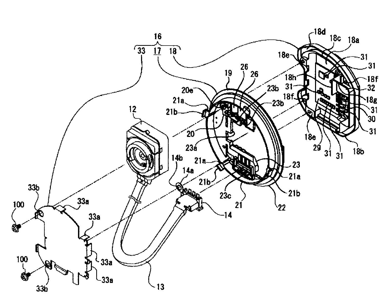
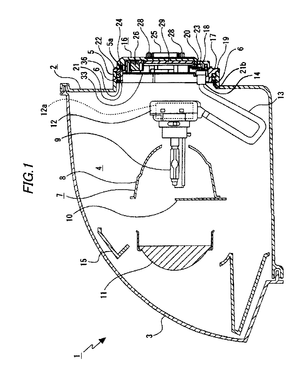
[0035]As is shown in FIG. 1, the vehicle headlamp 1 includes a lamp body 2 having a recess portion which is made to open forwards and a front cover 3 which closes a front opening of the lamp body 2, and an interior space defined by the lamp body 2 and the front cover 3 is defined as a lamp chamber 4.

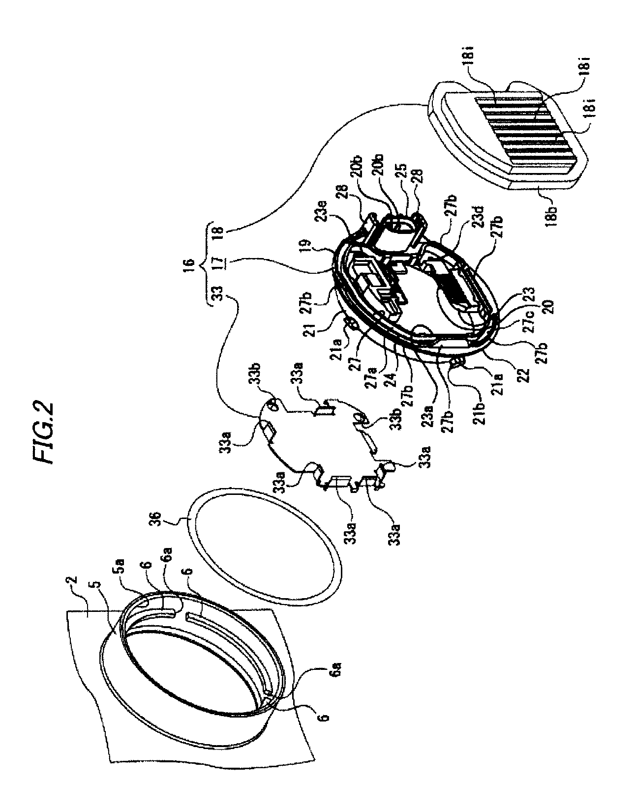
[0036]A cover mounting portion 5, which is formed into a substantially cylindrical shape, is provided at a rear end portion of the lamp body 2 (refer to FIG. 2). The cover mounting portion 5 has a mounting opening 5a which penetrates therethrough in a front-rear direction. Engagement portions 6, 6, . . . are provided on an inner surface of the cover mountin...


PUM

PropertyMeasurementUnit
voltageaaaaaaaaaa
electric poweraaaaaaaaaa
circumferenceaaaaaaaaaa

Abstract

A back cover (16) is attached to a cover mounting portion (5) of a lamp body (2) defining a lamp chamber (4) of a vehicle lamp (1). The back cover (16) is provided with a cover main body (19) to which a connection terminal (20) is partially embedded and a metallic case member (18) to which a circuit board (29, 30) is mounted. A seal groove (27) is formed on one of the cover main body (19) the case member (18).An elongated seal projection (18b) formed on the other of the cover main body (19) the case member (18). The elongated seal projection (18b) is fitted in the seal groove (27) and bonded to the seal groove (27), so that the elongated seal projection (18b) is fixed to the seal groove (27).

Description

BACKGROUND OF THE INVENTION[0001]1. Field of the Invention[0002]The present invention relates to a back cover and a method of assembling back cover method. The invention relates more particularly to a technical field in which a cover main body and a case member are connected together by an elongated seal projection which is bonded in such a state the projection is fitted in a seal groove so as to realize an improvement in mounting strength with which the case member is mounted on the case main body as well as an improvement in waterproofness therebetween.[0003]2. Background Art[0004]There are vehicle lamps in which a light source and an illumination circuit (a ballast) for driving the light source are disposed in a lamp chamber defined by a front cover and a lamp body (for example, refer to JP-A-2008-277008).[0005]A vehicle lamp described in JP-A-2008-277008 has a cover main body which is formed from a resin material and a heat dissipating member which is formed of a metallic materi...

Claims


Application Information

Patent Timeline
Patent Type & Authority Applications(United States)
IPC IPC(8): B60Q1/00H01R43/00
CPCB60Q1/007Y10T29/49002B60Q1/0094F21S45/48
Inventor YASHIKI, SATORUWATANABE, MASATO
Owner KOITO MFG CO LTD
Why Eureka
Try Eureka