
Sensor device

a sensor device and sensor technology, applied in the direction of instruments, fluid pressure measurement using piezoelectric devices, measurement apparatus components, etc., can solve the problems of detection accuracy reduction, detection failure, detection accuracy reduction, etc., and achieve the effect of preventing moisture infiltration

Active Publication Date: 2017-10-12
ALPS ALPINE CO LTD
View PDF3 Cites 4 Cited by
  • Summary
  • Abstract
  • Description
  • Claims
  • Application Information

AI Technical Summary

Benefits of technology

The present invention is a sensor device that prevents moisture from entering the device. It achieves this by using a functional film that is applied to the inner surface of a through-hole in the device's lid. This film is made hydrophobic, meaning it repels water from infiltrating through the hole. The functional film can be applied from the surface of the lid to the inner surface of the through-hole, providing effective protection against moisture. Additionally, the sensor device has potentials set to the reference potential of the circuit board, which ensures that the lid and frame provide electromagnetic shielding for the sensor. Overall, the sensor device is designed to prevent moisture infiltration and improve its overall performance.

Problems solved by technology

However, in a case where the through-hole is provided in the lid portion, moisture infiltrates into the inside through the through-hole, and the movement of the movable thin film is impeded, resulting in a problem of detection failure or a reduction in detection accuracy.
In addition, when the water or chemical is not dried and moisture remains, a reduction in detection accuracy is incurred.

Method used


Image

  • Sensor device
  • Sensor device
  • Sensor device

Examples


Embodiment Construction

[0021]Hereinafter, an embodiment of the present invention will be described with reference to the drawings. In the following description, like elements are denoted by like reference numerals, and description of members once described is appropriately omitted.

(Configuration of Sensor Device)

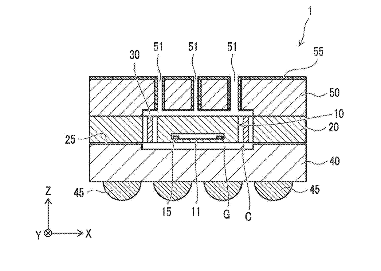
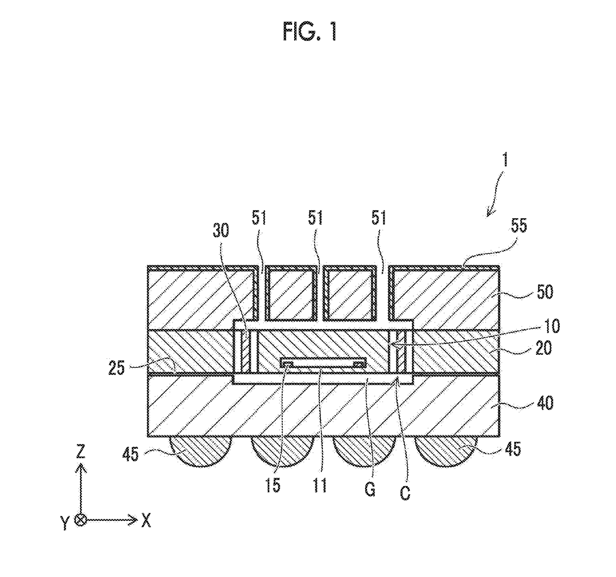
[0022]FIG. 1 is a sectional view illustrating a sensor device according to the embodiment.

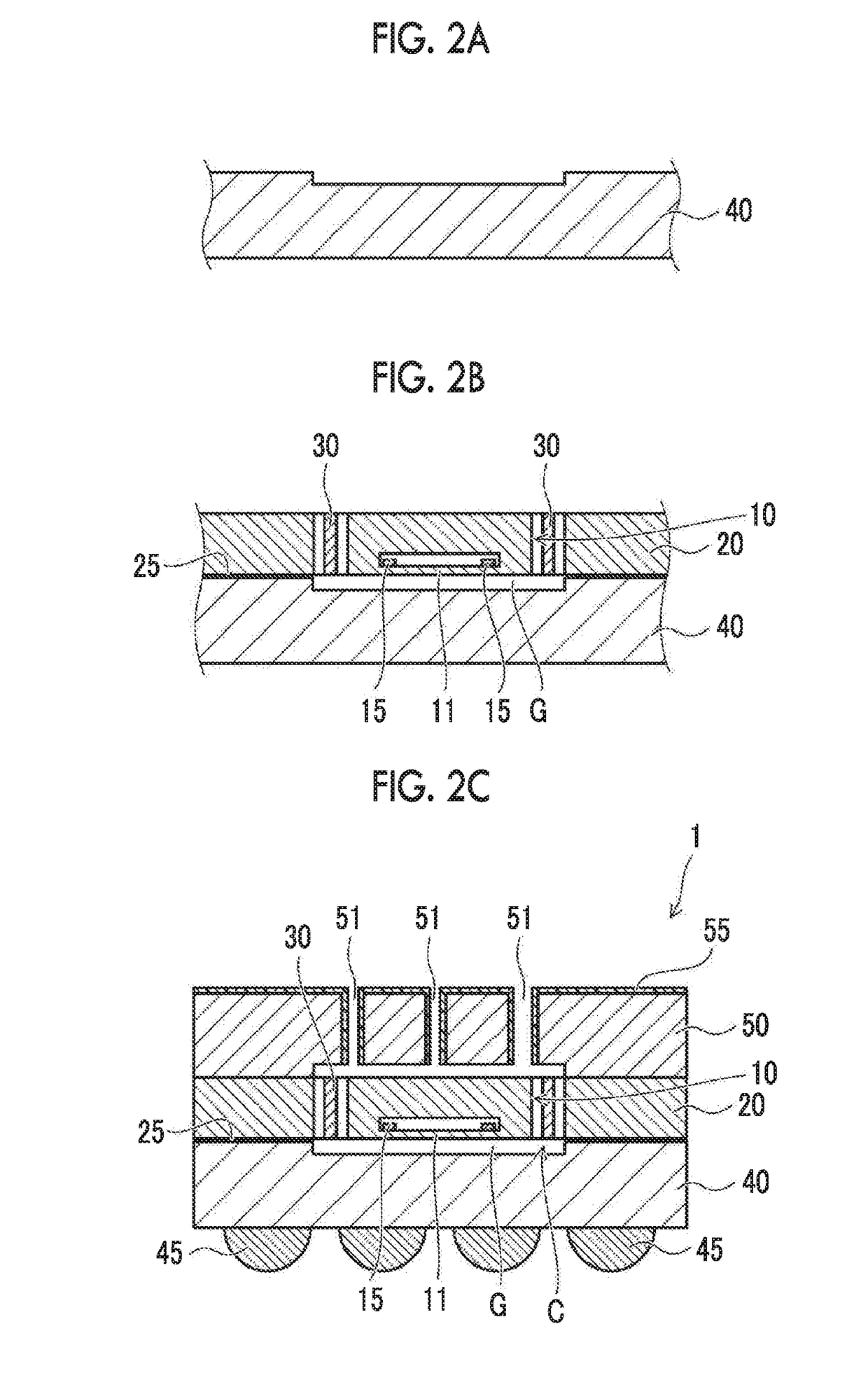
[0023]A sensor device 1 according to the embodiment includes a sensor portion 10 having a movable thin film 11 and a detection element 15 that outputs a signal corresponding to the displacement of the movable thin film 11. The detection element 15 of the sensor portion 10 is, for example, a piezoresistive element or a capacitive element. Accordingly, various physical quantities such as pressure, acceleration, temperature, humidity, and sound pressure are detected. In the embodiment, the sensor portion 10 is configured to detect pressure as an example.

[0024]The sensor device 1 includes a frame portion 20 dispo...


PUM


Abstract

A sensor device includes: a sensor portion having a movable thin film and a detection element configured to output a signal corresponding to displacement of the movable thin film; a frame portion disposed to surround an outside of the sensor portion; a circuit board including a circuit configured to process the signal output from the detection element; and a lid portion which is attached onto the frame portion and has a through-hole, in which a functional film having higher hydrophobicity than a surface of the lid portion is provided on at least an inner surface of the through-hole in the lid portion.

Description

CLAIM OF PRIORITY[0001]This application claims benefit of Japanese Patent Application No. 2016-078141 filed on Apr. 08, 2016, which is hereby incorporated by reference.BACKGROUND OF THE INVENTION1. Field of the Invention[0002]The present invention relates to a sensor device, and more particularly, to a sensor device including a detection element that outputs a signal corresponding to the displacement of a movable thin film.2. Description of the Related Art[0003]A sensor device in which a movable thin film is formed on a semiconductor substrate or the like by using a microelectromechanical systems (MEMS) technology and the displacement of the movable thin film is detected by a detection element is used in various fields as a small and highly accurate device.[0004]The movable thin film is formed, for example, by etching a semiconductor material such as silicon to form a cavity, and causing a thin silicon film to remain on the cavity. Accurately detecting the displacement of this movab...

Claims


Application Information

Patent Timeline
Patent Type & Authority Applications(United States)
IPC IPC(8): G01D11/24G01D11/26
CPCG01D11/26G01D11/245G01L9/0054G01L9/08
Inventor UMETSU, EIJI
Owner ALPS ALPINE CO LTD
Learn More