Touch-control display device

Inactive Publication Date: 2010-10-14
COMPAL ELECTRONICS INC
View PDF6 Cites 4 Cited by
  • Summary
  • Abstract
  • Description
  • Claims
  • Application Information

AI Technical Summary

Benefits of technology

[0016]Based on the depiction above, the touch-control panel in the present invention is disposed in the cavity of the frame, not on the top surface of the frame, so that the fault of producing fall between the touch-control panel and the frame can be reduced. Besides, the side surfaces of the touch-control panel and the side walls of the cavity

Problems solved by technology

In addition, during the assembling operation, if the touch-control panel 30 is pos

Method used


Image

  • Touch-control display device
  • Touch-control display device
  • Touch-control display device

Examples


Embodiment Construction

[0020]Reference will now be made in detail to the present preferred embodiments of the invention, examples of which are illustrated in the accompanying drawings. Wherever possible, the same reference numbers are used in the drawings and the description to refer to the same or like parts.

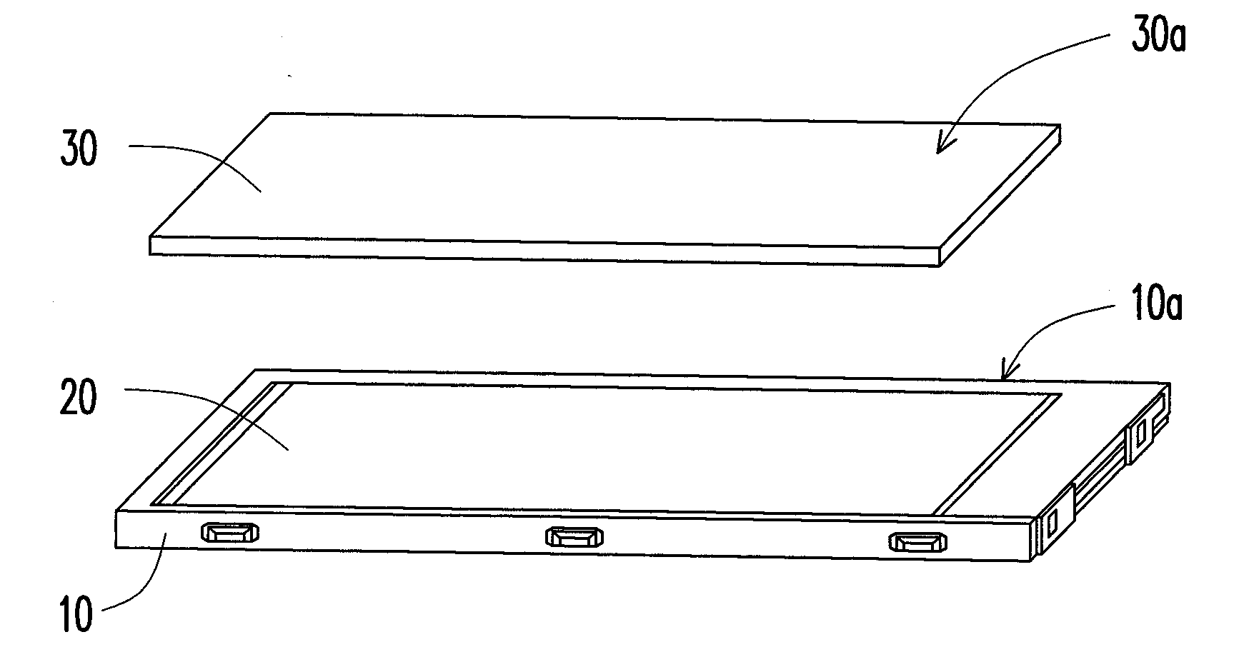
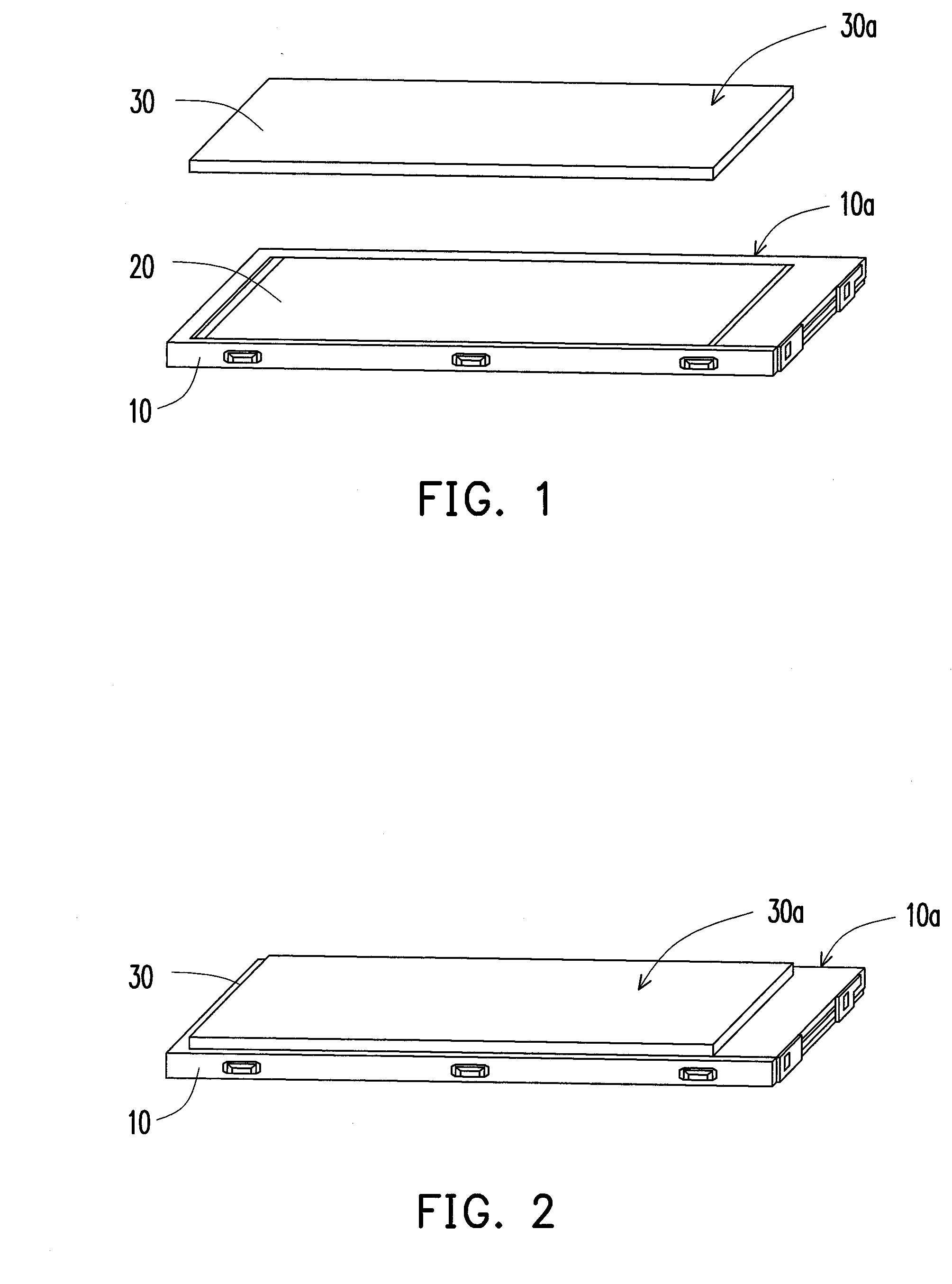
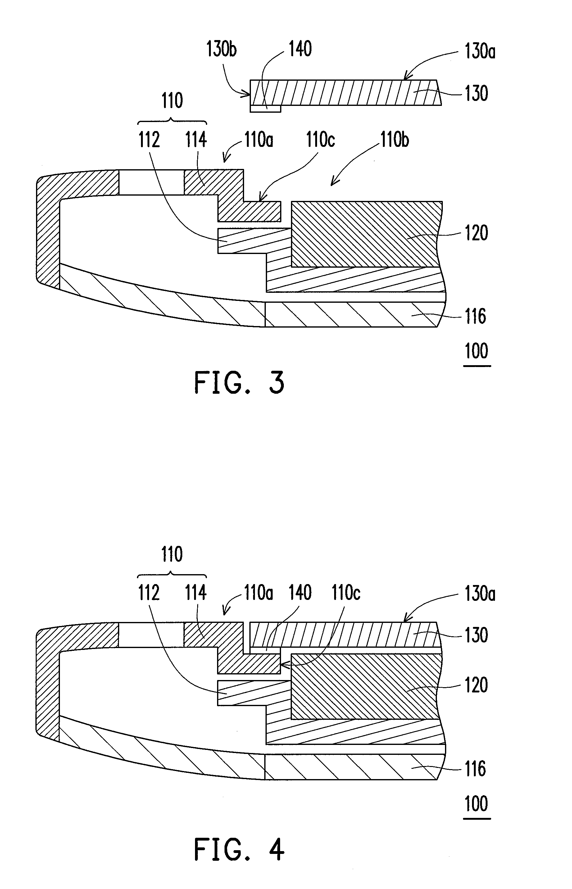
[0021]FIGS. 3 and 4 are respectively a local sectional diagram during assembling of a touch-control display device according to an embodiment of the present invention. Referring FIGS. 3 and 4, a touch-control display device 100 includes a frame 110, a display module 120 and a touch-control panel 130. The frame 110 includes a top surface 110a and a frame rim 110c extending from the top surface 110a. There is a step height between the top surface 110a and the frame rim 110c so as to form a cavity 110b, which means the top surface 110a joins downwards the frame rim 110c along the side wall of the cavity 110b so as to form a stepped surface.

[0022]The touch-control panel 130 is disposed in the cavity 110b...


PUM


Abstract

A touch-control display device includes a frame, a touch-control panel and a display module. The frame has a top surface and a frame rim extending from the top surface, wherein there is a step height between the top surface and the frame rim so as to form a cavity. The touch-control panel is disposed in the cavity and the frame rim supports at least two sides of the touch-control panel. The display module is disposed in the frame and correspondingly assembled under the touch-control panel.

Description

CROSS-REFERENCE TO RELATED APPLICATION[0001]This application claims the priority benefit of U.S. Provisional application Ser. No. 61 / 168,237, filed on Apr. 10, 2009. The entirety of the above-mentioned patent application is hereby incorporated by reference herein and made a part of specification.BACKGROUND OF THE INVENTION1. Field of the Invention[0002]The present invention generally relates to a display, and more particularly, to a touch-control display device.2. Description of Related Art[0003]The conventional display with a touch-control panel mostly uses a bi-sides tape to fix in adhesion the touch-control panel on a frame enclosing a display module.[0004]FIGS. 1 and 2 are respectively an assembly diagram of a conventional touch-control display device. Referring to FIGS. 1 and 2, the touch-control display device includes a frame 10, a display module 20 fixed in the frame 10 and a touch-control panel 30 fixed on the frame 10. During assembling, the display module 20 is firstly fi...

Claims


Application Information

Patent Timeline
IPC IPC(8): G06F3/045G06F3/041
CPCG06F3/041G06F1/1643G06F1/1626
Inventor LIN, YU-YUAN
Owner COMPAL ELECTRONICS INC
Why Eureka
Try Eureka