Thin film fuel cell assembly

a fuel cell and thin film technology, applied in the direction of fuel cells, electrochemical generators, electrical equipment, etc., can solve the problems of increasing the weight and size increasing and increasing the cost of the fuel cell, so as to reduce the contact resistance of the fuel cell and reduce the weight and size. , the effect of compact siz

Inactive Publication Date: 2007-05-10
SHANGHAI HORIZON FUEL CELL TECH
View PDF6 Cites 37 Cited by
  • Summary
  • Abstract
  • Description
  • Claims
  • Application Information

AI Technical Summary

Benefits of technology

[0010] One objective of certain embodiments of the invention is to reduce the fuel cell's contact resistance between layers without clamping the fuel cell or applying thin film deposition technology, so that a very light weight and very compact size fuel cell can be manufactured.

Problems solved by technology

One major shortcoming of such conventional fuel cell assemblies is contact resistance between layers of material in the fuel cell and layers of different fuel cells, which causes power loss and internal heat generation.
This is an effective approach to reduce contact resistance, however it adds significant complexity, weight and size to the fuel cell, making it not suitable for portable applications where light weight and compact size are required.
One additional problem found in conventional fuel cell assemblies is that reactant gas flow channels need to be machined, etched or molded on the plates.
The gas flow channels create sealing problems and add weight, size and cost to the fuel cell.
Compared to conventional technologies, those prior art systems do have improvements in the area of fuel cell power density, especially for fuel cells less than 10 watts, however, those thin film coating technologies are still very complicated and costly, not suitable for mass producing low cost fuel cells.

Method used


Image

  • Thin film fuel cell assembly
  • Thin film fuel cell assembly
  • Thin film fuel cell assembly

Examples


example 1

[0030] A 5 cm×5 cm highly conductive and high polymer content gas diffusion layer is laminated to a 5 cm×5 cm titanium film (porous current collector) under pressure of 200 B and temperature of 160° C. for 1 minute. A catalyst ink with a Pt loading of 0.4 mg / cm2 is coated to the gas diffusion layer. The laminated and catalyst coated material is cut into four pieces, each with a size of 2.5 cm×2.5 cm. A 5.5 cm×2.5 cm proton exchange membrane is placed in between the two pieces and laminated at below 200 Bar and at a temperature of 160 C for 2 minutes. A membrane electrode assembly and current collector sub-unit with two cells is produced.

[0031] The sub-unit is placed in two pieces of plastics frame and laminated. Then a non-porous plastic film is further laminated to the anode side of the sub-unit and a hydrogen inlet needle and a hydrogen outlet needle are installed on the fuel cell unit.

[0032] After supplying hydrogen to the fuel cell and connecting it to a load, a voltage of 1.4...

example 2

[0033] A 2.5 cm×2.5 cm CCM is sandwiched between two 2.5 cm×2.5 cm highly conductive and high polymer content gas diffusion layers, and two 2.5 cm×2.5 cm titanium film (porous current collector) are disposed on the outer sides of both gas diffusion layers. The entire five layers are laminated under a pressure of 200 Bar and at a temperature of 160° C. for 2 minutes, to form a membrane electrode assembly and current collector sub-unit.

[0034] The sub-unit is placed in two pieces of plastics frame and laminated. Then a non-porous plastics film is further laminated to the anode side of the sub-unit and a hydrogen inlet needle and a hydrogen outlet needle are installed on the fuel cell unit.

[0035] After supplying hydrogen to the fuel cell and connecting it to a load, a voltage of 0.7 and current of 0.15 A are observed.

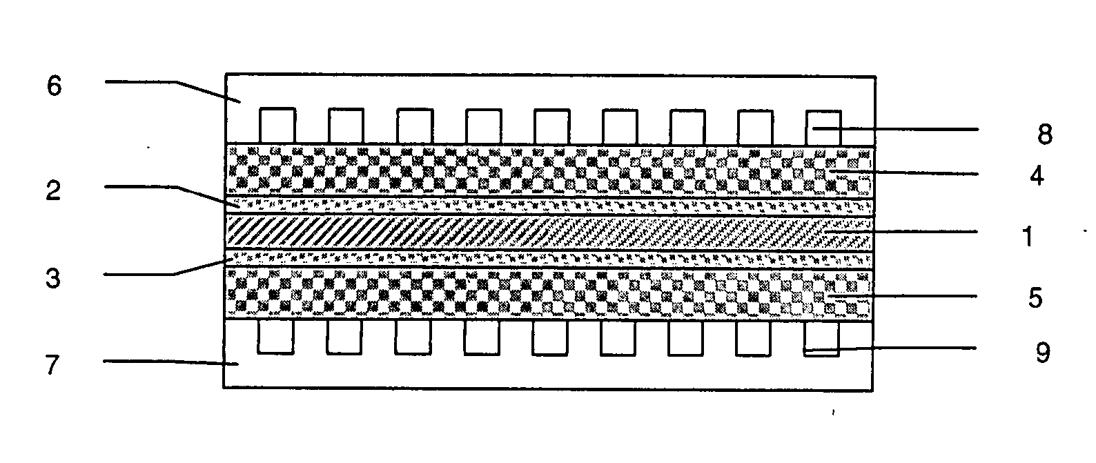
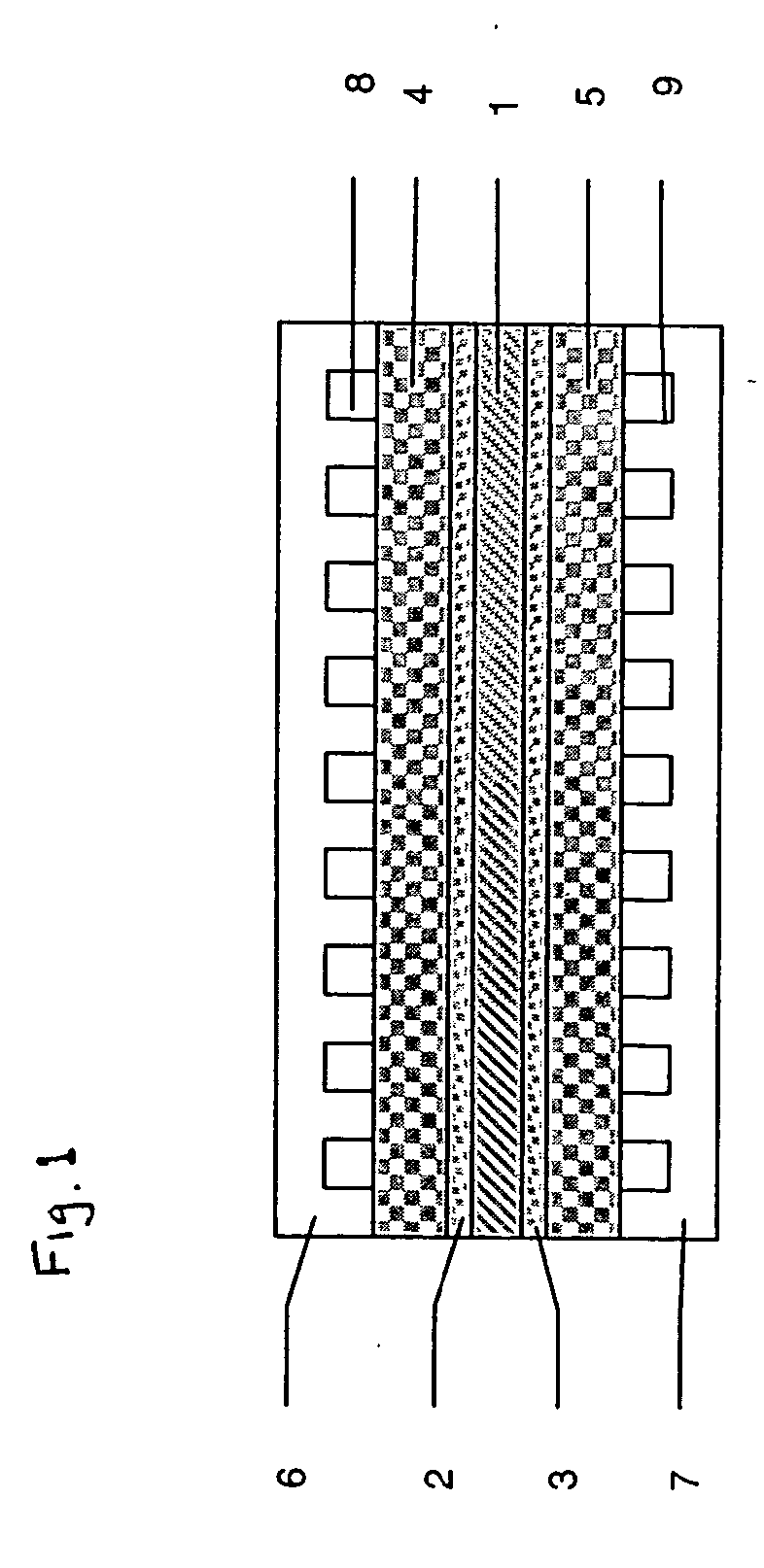
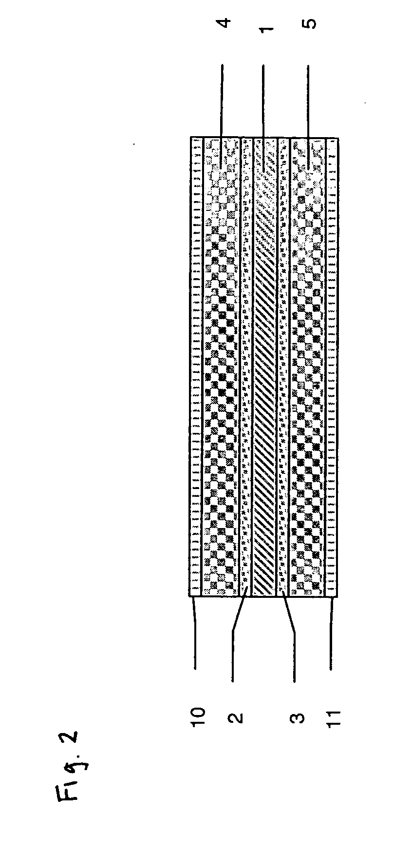
[0036]FIG. 4 shows double cell unit. It includes membrane 1, catalyst layers 2, 3 on both sides of the membrane, gas diffusion layers 4, 5 on sides of both catalyst laye...


PUM

PropertyMeasurementUnit
melting temperatureaaaaaaaaaa
temperatureaaaaaaaaaa
sizeaaaaaaaaaa

Abstract

A fuel cell assembly including: a membrane electrode assembly and current collector sub-unit including (i) a polymer electrolyte membrane having a cathode side and an anode side; (ii) catalyst layers disposed, respectively, on both sides of the polymer electrolyte membrane; (iii) gas diffusion layers disposed, respectively, on sides of both catalyst layers, wherein the gas diffusion layers are laminated on the catalyst layers; and (iv) porous current collectors disposed, respectively, on sides of both gas diffusion layers, wherein the porous current collectors are laminated on the gas diffusion layers. The fuel cell assembly also includes a hydrogen supplier layer disposed on the anode side of the sub-unit, sealed to the edges of the sub-unit and forming an anode chamber; and a hydrogen inlet and a hydrogen outlet connected the anode chamber.

Description

[0001] This application claims the benefit of U.S. Provisional Application No. 60 / 729,951, filed Oct. 25, 2005, the contents of which are incorporated herein by reference.TECHNICAL FIELD [0002] This invention relates to fuel cell assemblies. BACKGROUND OF THE INVENTION [0003] Proton exchange membrane (PEM) fuel cells are electrochemical devices that convert chemical energy of hydrogen into electrical energy without combustion. They have high potential to offer an environmentally friendly, high-energy density, efficient, and renewable power source for various applications from portable devices to vehicles and stationary power plants. [0004] PEM fuel cells operate at relatively low temperatures, have higher power density than direct methanol fuel cells, and can quickly respond to changes in power demand. For portable power applications, PEM fuel cells might be light weight and compact size to compete with conventional batteries, and various arts have been developed and are being devel...

Claims


Application Information

Patent Timeline
Patent Type & Authority Applications(United States)
IPC IPC(8): H01M4/94H01M4/96
CPCH01M8/0232H01M8/0234H01M8/0239H01M8/0273H01M8/1002H01M8/242Y02E60/521H01M8/1007Y02E60/50
Inventor GU, ZHIJUNWU, DERONG
Owner SHANGHAI HORIZON FUEL CELL TECH
Why Eureka
Try Eureka