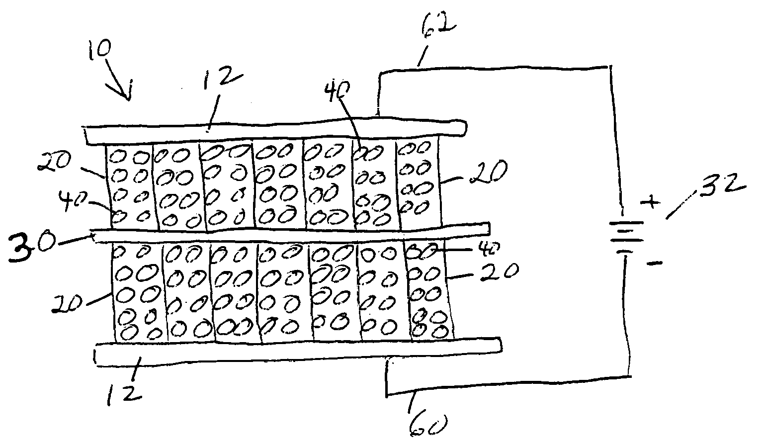
[0020] When an electrical potential is applied between the two electrodes, the resulting
electric field causes negative electrolyte ions to move toward the positive electrode and positive electrolyte ions to move toward the negative electrode. These ions coat the electrode surfaces. Each
ion is paired with on opposing charge on the electrode surface, and the buildup of these charges results in an
electrical current flow into the device terminals. The energy represented by this current (the integral of current times
voltage) is stored in the electrical field between the electrolyte ions and the charge on the plates. In this regard, the device behaves like an ultracapacitor, wherein the large electrode surface area and the small effective distance between the opposing charges yield a very
high capacitance. In addition, because the nanostructures in the aligned array have
diameter and spacing comparable to the dimension of an
ion of the electrolyte, the ions can completely populate the interstices between the nanostructures. This aspect of the process is much the same as the way nature stores energy when ions plate out in an electrochemical battery. The structure of the invention can therefore achieve an
energy density (greater than 30 Wh / kg) that is equivalent to several types of batteries. The
energy storage device of the invention also offers instantaneous
power density up to three orders of magnitude higher (greater than 30 kW / kg) than either batteries or
fuel cells, practically unlimited lifetime (greater than 300,000 cycles), exceedingly high
immunity to shock and vibration, limited temperature dependence, and near unity charging and discharging efficiency.
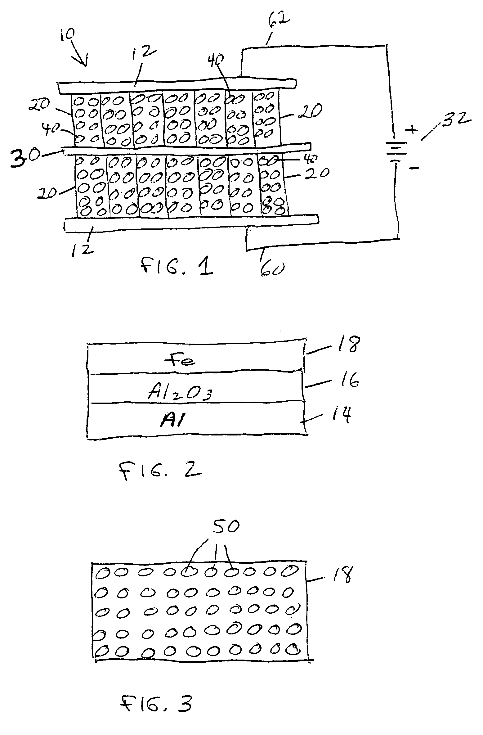
[0021] The engineered structures of the invention provide up to a two orders of magnitude increase in electrode surface area while maintaining uniform pore sizes that are well matched to the
diameter of the electrolyte ions. Calculations indicate that the resulting energy storage density will be substantially equivalent to that of a conventional storage battery. At the same time, low
contact resistance and ballistic transport exhibited by the structure of the invention results in improved
power density while its high purity results in increased
operating voltage and enhanced
energy density. The engineered structures of the invention use more environmentally-friendly materials than a traditional battery. The design of the structures disclosed herein lends itself to
mass production and costs are expected to be low.
[0022] Several phenomena associated with the engineered nanostructures and devices of the invention enhance performance.
Nanotube conduction exhibits a phenomenon known as ballistic transport or
quantum conduction so that the effective resistivity of the
nanotube is extremely low. This situation is in contrast to the structure and bonding of
activated carbon that leads to relatively
high resistivity in conventional double layer capacitors. The
quantum behavior of the
nanotube structures according to embodiments of the invention provide a
high density of
electronic states at the surface of the tube as compared to
low density of
electronic states of
activated carbon structures in a traditional DLC that provides a limited number of
electron sites thereby limiting capacity. The structures according to the invention exhibit regular and controlled spacing allowing electrolyte access to the entire surface area unlike the highly non-uniform pore size in prior art
activated carbon DLCs. Further, carbon nanotubes, with no defects, are expected to sustain on the order of 4 V as compared with prior art DLCs in which the activated carbon contains impurities and defects that react with the electrolyte to limit the maximum
breakdown voltage to about 2.6 V. The increased
voltage results in a 2.5:1 increase in energy storage density.

