

Cold cathode tube lamp, lighting device, and display device
- Summary
- Abstract
- Description
- Claims
- Application Information
AI Technical Summary
Benefits of technology
Problems solved by technology
Method used
Image

Examples
Embodiment Construction
[0090] Hereinafter, preferred embodiments of the present invention will be described with reference to the drawings. Since the inner structure (including those enclosed) of a cold cathode tube lamp according to the present invention is not an essential part of the present invention, various known structures, arrangements and arts of the cold cathode tube lamp are applicable and thus it is omitted from the detailed description.
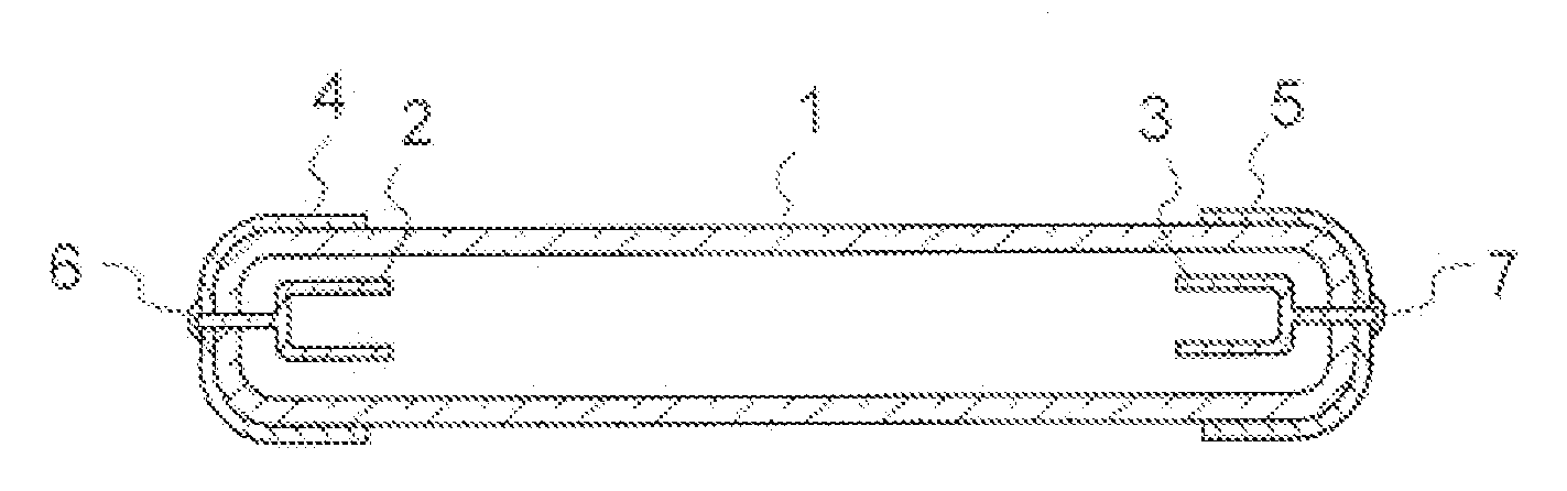
[0091] First, a first preferred embodiment of the present invention will be described. FIG. 1 is a schematic sectional view of a cold cathode tube lamp according to the first preferred embodiment of the present invention. In FIG. 1, portions which are the same as those shown in FIG. 21 are provided with the same numerals and are thus omitted from the detailed description. The cold cathode tube lamp shown in FIG. 1 is preferably constructed by providing external electrodes 4 and 5 at the end portions of the glass tube 1 of the conventional cold cathode tube lam...
PUM
 Abstract
Description
Claims
Application Information