Multilayer ceramic capacitor

a ceramic capacitor and multi-layer technology, applied in the direction of fixed capacitors, stacked capacitors, fixed capacitor details, etc., can solve the problems of large electrostatic capacitance that cannot be guaranteed, difficult to ensure moisture resistance, and inability to ensure large electrostatic capacitance, etc., to achieve the effect of increasing electrostatic capacitan

Active Publication Date: 2019-11-21
MURATA MFG CO LTD
View PDF0 Cites 23 Cited by
  • Summary
  • Abstract
  • Description
  • Claims
  • Application Information

AI Technical Summary

Benefits of technology

[0026]According to preferred embodiments of the present invention, small-sized multilayer ceramic capacitors each capable of ensuring moisture resistance and increasing electrostatic capacitance are able to be obtained.

Problems solved by technology

Therefore, in the case in which no measure is taken, a large electrostatic capacitance may fail to be ensured.
If the inner layer portion provided inside the laminate is increased in size in order to reduce the size of the laminate while electrostatic capacitance is ensured, the margin is inevitably reduced in thickness, which makes it difficult to ensure the moisture resistance described above.
Even if the pair of external electrodes are each reduced in thickness in order to increase the size of the laminate within a limited range, it may be difficult to ensure the moisture resistance described above.
To reduce the size of the multilayer ceramic capacitor, however, merely providing the alloy layers as disclosed in Japanese Patent Application Laid-Open No. 2015-35581 may not necessarily sufficiently ensure moisture resistance.
That is, for example, as disclosed in Tables 1 and 2 of Japanese Patent Application Laid-Open No. 2015-35581, there may be some cases of failing to sufficiently ensure moisture resistance in spite of increasing the coverage ratio of the alloy layer as well as providing the alloy layers on the end surfaces of the laminates.
As described above, sufficient moisture resistance may not be ensured by covering the end surfaces of the laminates with the alloy layers.

Method used


Image

  • Multilayer ceramic capacitor
  • Multilayer ceramic capacitor
  • Multilayer ceramic capacitor

Examples


Embodiment Construction

[0040]Preferred embodiments according to the present invention will be described in detail below with reference to the drawings. In the preferred embodiments described below, the same or common portions are denoted by the same reference numerals in the drawings, and description thereof is not repeated.

Configuration of Multilayer Ceramic Capacitor According to a Preferred Embodiment of the Present Invention

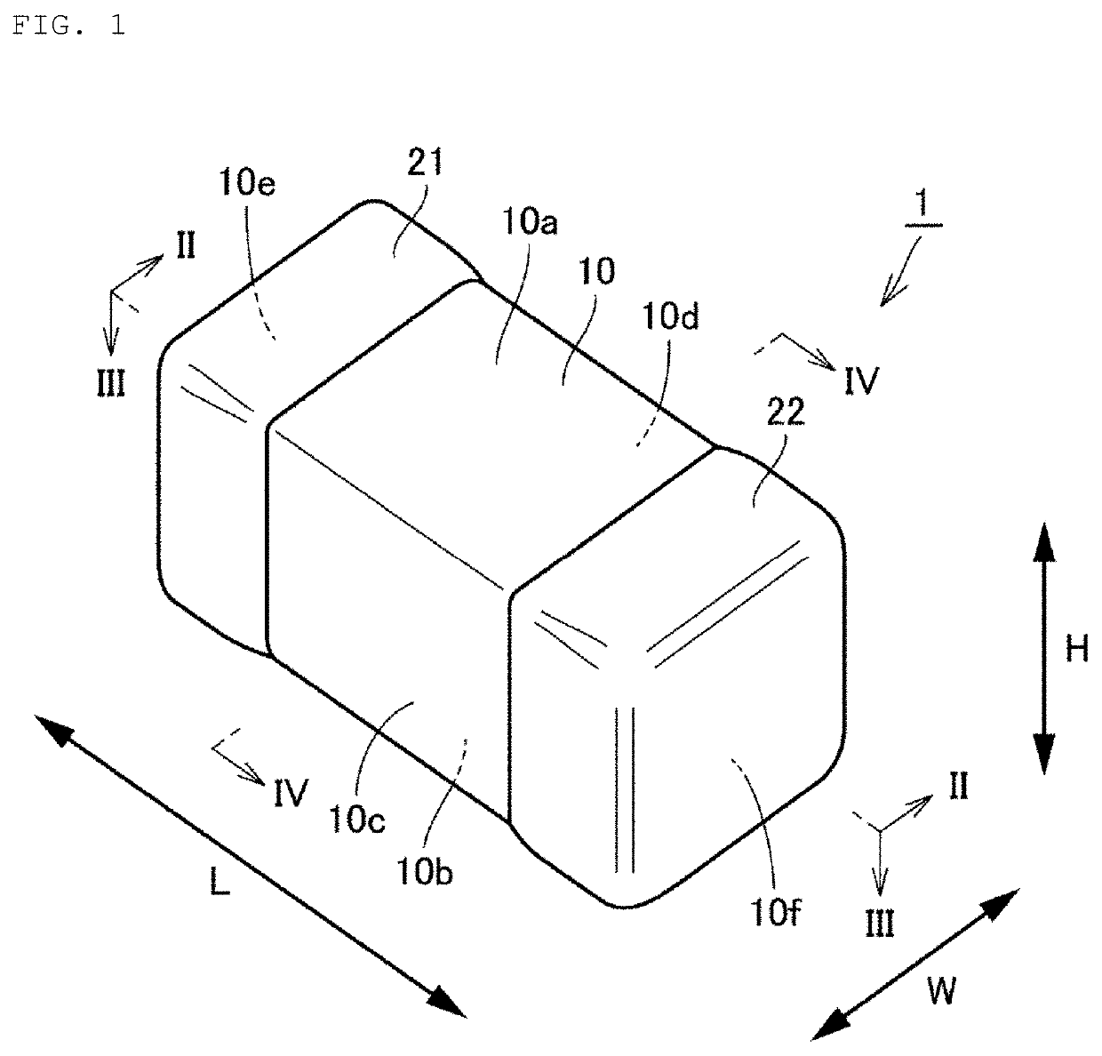
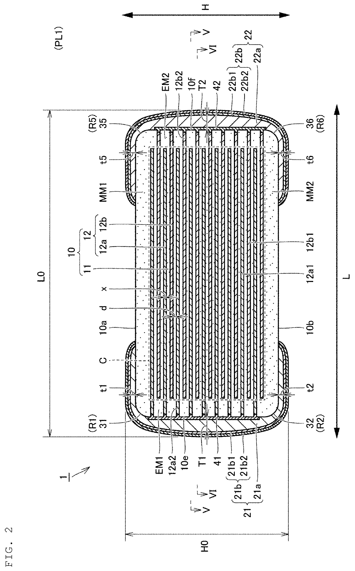
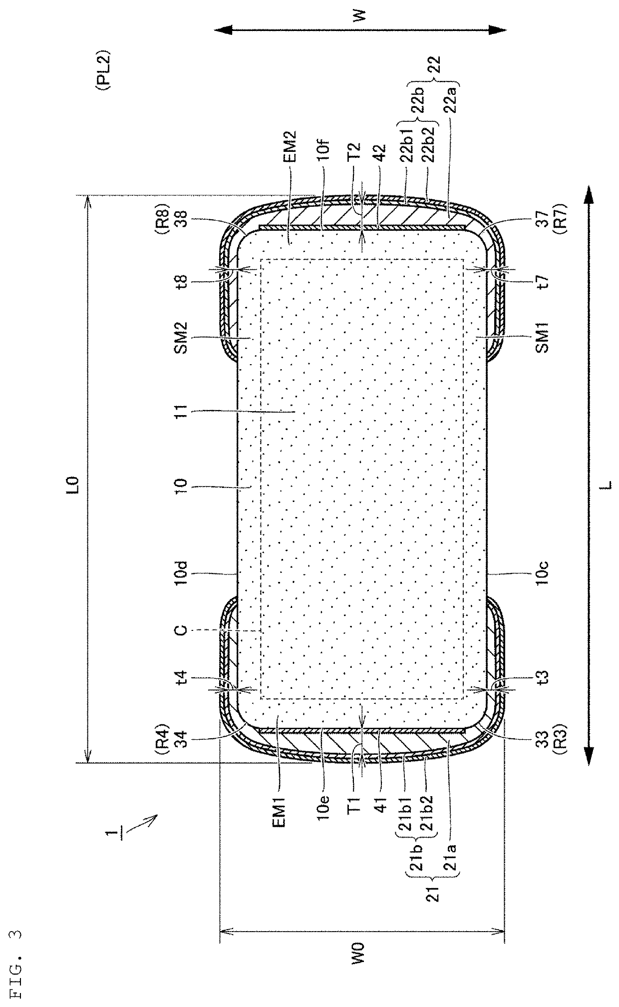
[0041]FIG. 1 is a diagrammatic perspective view of a multilayer ceramic capacitor according to a preferred embodiment of the present invention. FIGS. 2 to 4 are schematic cross-sectional views taken along lines II-II, III-III, and IV-IV, respectively, shown in FIG. 1. FIGS. 5 and 6 are schematic cross-sectional views taken along respective lines V-V and VI-VI shown in FIG. 2. FIG. 7 is an electron micrograph of a cross section of a main portion of the multilayer ceramic capacitor shown in FIG. 1 before a plating film is provided, and FIG. 8 is a schematic view of the electron micro...


PUM

PropertyMeasurementUnit
curvature radius R4aaaaaaaaaa
curvature radius R8aaaaaaaaaa

Abstract

A multilayer ceramic capacitor includes a laminate including dielectric layers and internal electrode layers, and first and second external electrodes respectively including first and second base electrode layers. The internal electrode layers, and the first and second base electrode layers are connected through first and second alloy layers that cover first and second end surfaces of the laminate. A predetermined portion of ridges between each of the first and second end surfaces, and each of first and second principal surfaces and first and second side surfaces, among ridges of the laminate, has a curvature radius of about 5.4 μm or more and about 10 μm or less, and the first and second external electrodes extend from the first and second end surfaces to cover the ridges.

Description

CROSS REFERENCE TO RELATED APPLICATIONS[0001]This application claims the benefit of priority to Japanese Patent Application No. 2018-094776 filed on May 16, 2018. The entire contents of this application are hereby incorporated herein by reference.BACKGROUND OF THE INVENTION1. Field of the Invention[0002]The present invention relates to a multilayer ceramic capacitor, and more particularly to a multilayer ceramic capacitor having a chip that is significantly reduced in size.2. Description of the Related Art[0003]In recent years, reductions in the size of multilayer ceramic capacitors have been greatly advancing, and a multilayer ceramic capacitor having an external dimension in the length direction of approximately 0.4 mm and in the width and height directions of approximately 0.2 mm, that is, having a 0402 chip size, has been practically used.[0004]In general, a multilayer ceramic capacitor includes a laminate including internal electrode layers and dielectric layers alternately lam...

Claims


Application Information

Patent Timeline
Patent Type & Authority Applications(United States)
IPC IPC(8): H01G4/232H01G4/30
CPCH01G4/008H01G4/1227H01G4/30H01G4/1236H01G4/2325H01G4/232
Inventor HARADA, TOSHIHIRO
Owner MURATA MFG CO LTD
Why Eureka
Try Eureka