
Push switch and method of manufacturing the same

a technology of push switch and push switch body, which is applied in the field of push switch, can solve the problems of infiltration of the main switch unit, difficulty in filling the interior gaps between the resin and the inner side of the switch case, so as to achieve reliable waterproofing, reduce assembly time, and improve productivity.

Inactive Publication Date: 2012-06-28
TOKYO PARTS IND CO LTD
View PDF7 Cites 4 Cited by
  • Summary
  • Abstract
  • Description
  • Claims
  • Application Information

AI Technical Summary

Benefits of technology

[0008]Thus, the present invention provides a push switch with which the waterproofness of the push switch can be improved, and with which productivity can be improved.
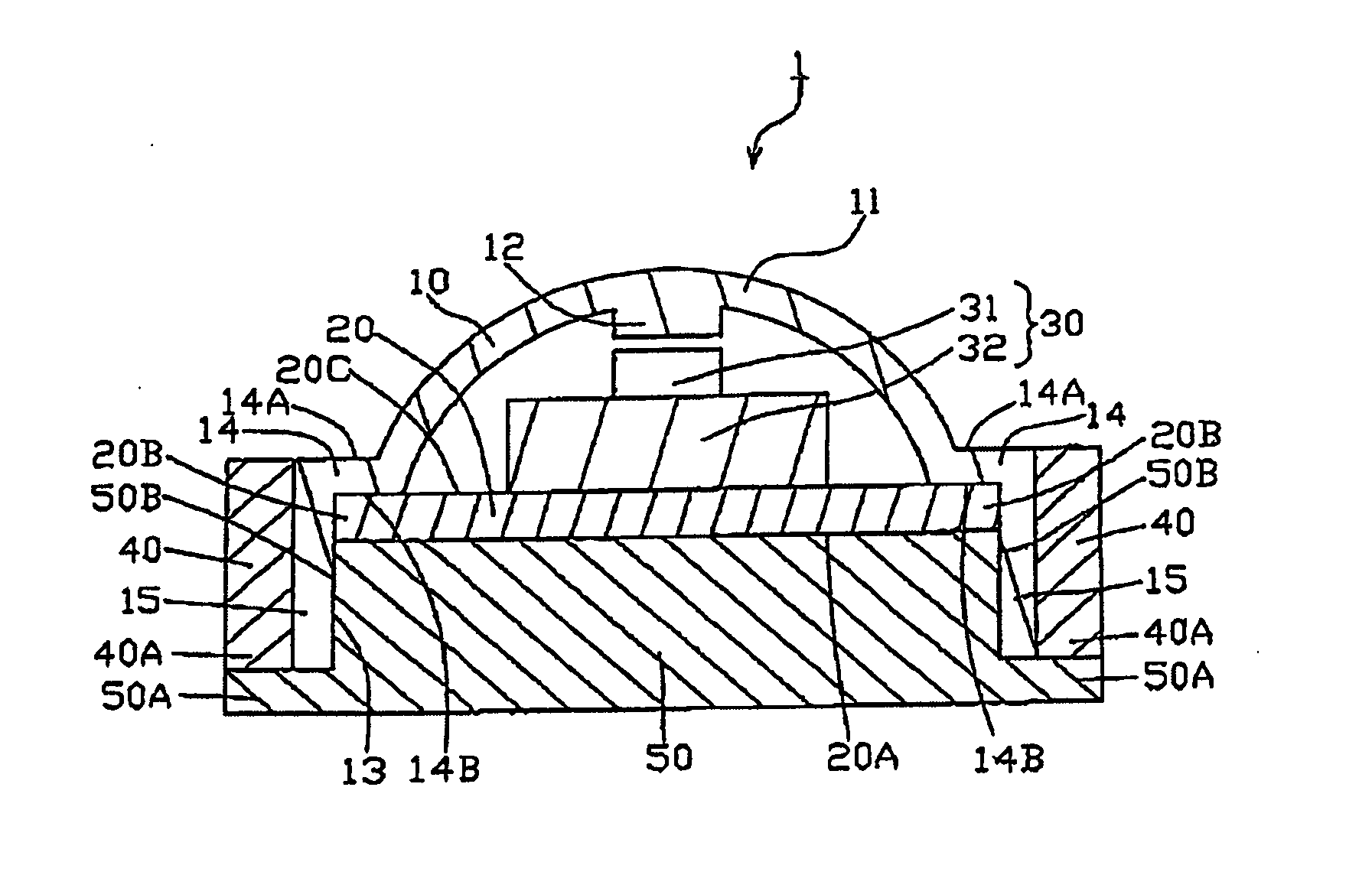
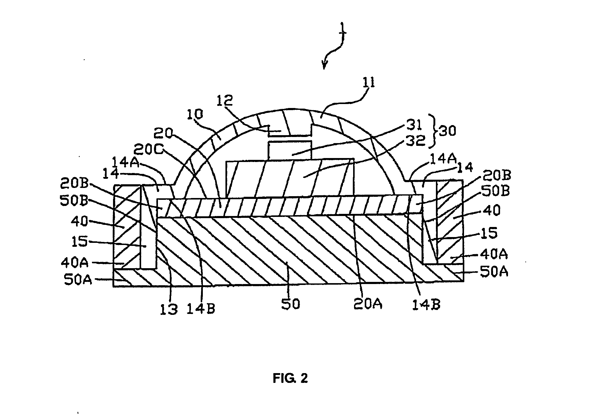
[0014]With the present invention, the outer circumferential face of the side wall of the button and the bottom of the switch substrate or a region below the switch substrate are covered by integrally molded resin. Thus the interior of the button is sealed and reliable waterproofing can be achieved. Furthermore, the conventional work of injecting thermosetting resin is not required, so that the time required for assembly can be greatly reduced and productivity can be markedly improved.

Problems solved by technology

However, in methods where the resin is applied (injected) into the switch case, it is difficult to fill the interior of the switch case without gaps, and thus gaps may occur between the resin and the inner side of the switch case.
In this event, if drops of water adhere to the bottom of the switch case, there is a risk that these drops of water will infiltrate the main switch unit, which reduces the waterproofness of the push switch.
Furthermore, the work of applying the thermosetting resin requires much time and skill, which greatly reduces productivity.

Method used


Image

  • Push switch and method of manufacturing the same
  • Push switch and method of manufacturing the same
  • Push switch and method of manufacturing the same

Examples


embodiment

Third Mode of Embodiment

[0071]FIG. 7 is a sectional view of a push switch according to a third mode embodiment of the present invention.

[0072]FIG. 8(a) is a sectional view showing the situation in which the button bearing the switch substrate has been inserted into the forming mold according to the third mode of embodiment of the present invention. FIG. 8(b) is a sectional view of the situation in which the forming mold according to the third mode of embodiment of the present invention has been closed. FIG. 8(c) is a sectional view of the situation in which the resin has been injected into the forming mold according to the third mode of embodiment of the present invention. In FIG. 7 and FIG. 8, identical reference numerals have been used for components identical to those in the first mode of embodiment, and redundant description of the same has been omitted.

[0073]The differences between the present mode of embodiment and the first mode of embodiment will be explained. In the first m...


PUM

PropertyMeasurementUnit
flexibleaaaaaaaaaa
circumferenceaaaaaaaaaa
shapeaaaaaaaaaa

Abstract

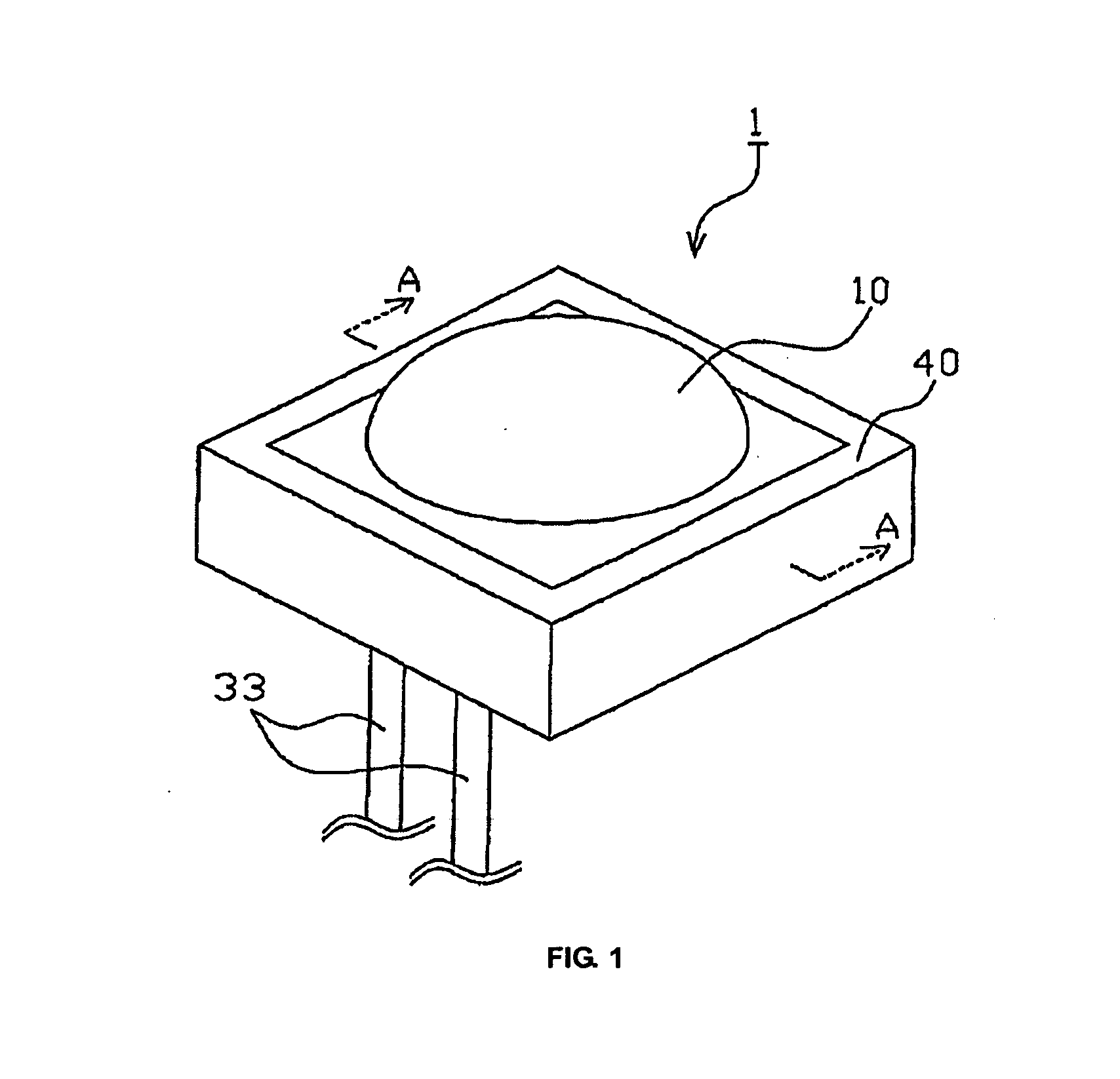
A push switch comprising: a button made of a flexible material having a cap shaped top operation part, a flat part formed extending laterally from an edge of an opening in the top operation part, and a side wall formed extending downward from an outer edge of the flat part; a switch substrate fitted in close contact with the inner circumference of the side wall and abutting the bottom face of the flat part of the button; and a switch arranged inside the button, on the switch substrate, wherein the outer circumferential face of the side wall of the button and the bottom face of the switch substrate are covered by integrally molded resin.

Description

BACKGROUND OF THE INVENTION[0001]1. Field of the Invention[0002]The present invention relates to a push switch.[0003]2. Description of the Related Art[0004]Conventional push switches include, for example, switch operation devices that are installed in vehicles and operated by pressing from the exterior (Japanese Patent Laid-Open Publication No. 2008-10360). As shown in FIG. 10(a) and FIG. 10(b), this push switch comprises a switch case 101, made from hard resin, a switch button 102, made from soft resin, and a main switch unit 107.[0005]This switch case 101 is formed as a rectilinear box having a space at the interior for receiving the switch button 102. The main switch unit 107 is assembled at the interior of the switch button 102, and a thermosetting resin 111 is applied at the interior of the switch case 101. This thermosetting resin 111 solidly fixes the main switch unit 107 in place in the switch case 101 and the switch button 102, and allows for waterproofing of the main switc...

Claims


Application Information

Patent Timeline
Patent Type & Authority Applications(United States)
IPC IPC(8): H01H13/14H01H11/00
CPCH01H13/06H01H11/0018Y10T29/49105
Inventor YASHIMA, TETSUSHI
Owner TOKYO PARTS IND CO LTD
Learn More