Manufacturing method for in-mold injection 3D coil product and 3D coil product

A technology of in-mold injection molding and manufacturing method, which is applied to coil devices, induction heating, etc., can solve problems such as intelligent and precise control of heat, air pressure and moisture, inability to perform precise temperature control, and low power density, and achieve reliable waterproofing. , good protection, high heating efficiency

Inactive Publication Date: 2015-12-16
GUANGDONG JANUS SMART GRP CO LTD +1
View PDF8 Cites 4 Cited by
  • Summary
  • Abstract
  • Description
  • Claims
  • Application Information

AI Technical Summary

Problems solved by technology

The heating coils of ordinary electrical products generally have the disadvantages of uneven heating and inability to perform precise temperature control
The traditional 2D coil heating method will lead to high heat loss. For example, the traditional electric heating pan heats the bottom of the inner pot, and the heat is conducted from the bottom to the upper part through contact conduction. The disadvantages of this are slow heating, uneven heating, and more Not to mention intelligent and precise control of heat, air pressure and moisture
In addition, there is another big disadvantage of resistance wire heating, which is that it needs to generate heat itself, and the power density it can withstand is low, so it cannot adapt to some heating occasions that require higher temperature.
Therefore, the existing coil products can no longer meet people's needs

Method used


Image

  • Manufacturing method for in-mold injection 3D coil product and 3D coil product
  • Manufacturing method for in-mold injection 3D coil product and 3D coil product
  • Manufacturing method for in-mold injection 3D coil product and 3D coil product

Examples


Embodiment Construction

[0028] Embodiments of the present invention will be described in detail below. It should be emphasized that the following description is only exemplary and not intended to limit the scope of the invention and its application.

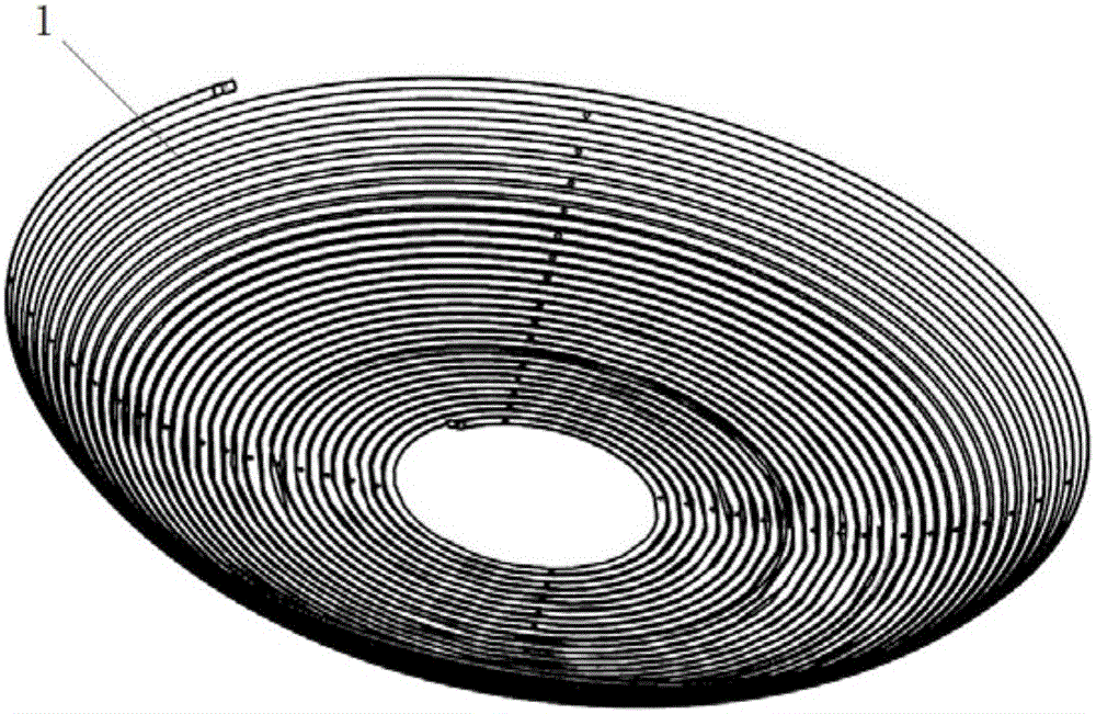
[0029] refer to Figure 1 to Figure 4 , in one embodiment, a method for manufacturing an in-mold injection molded 3D coil product, comprising the following steps:

[0030] a. Process the metal material into a 3D coil 1 with a multi-circle surrounding distribution in the shape of a pot as a whole;

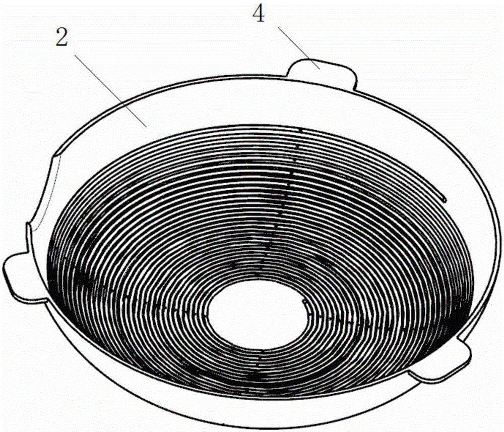
[0031] b. Injection molding the injection molded part 2 on one side of the 3D coil 1;

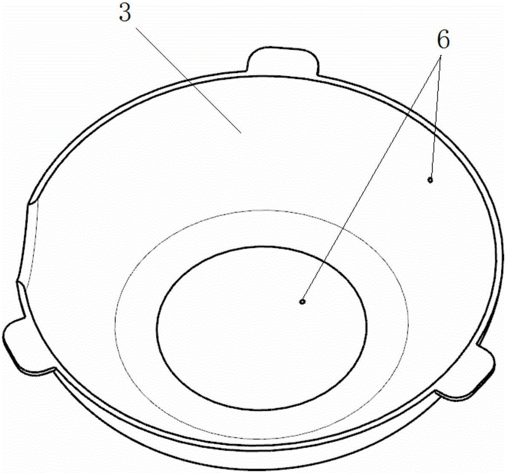
[0032] c. Perform secondary injection molding on the 3D coil 1 , and cover the 3D coil 1 with secondary injection molding material 3 , exposing only two contacts 6 as positive and negative poles of the coil.

[0033] In different embodiments, in step a, the 3D coils can be distributed in a circle with multiple turns (such as Figure 1-2 shown), square or polygonal, etc...


PUM

PropertyMeasurementUnit
thicknessaaaaaaaaaa

Abstract

A manufacturing method for an in-mold injection 3D coil product comprises the following steps that a, a metal material is machined to form a 3D coil, the overall contour of the 3D coil is in a pot shape, and multiple circles of wires of the 3D coil are distributed in a surrounding mode; b, an injection molding piece is formed on one side of the 3D coil through integrated injection molding; and c, secondary injection molding is conducted on the 3D coil to cover the 3D coil, and only two contacts of the positive pole and the negative pole of the coil are exposed. The in-mold injection 3D coil product comprises the 3D coil with the overall contour being in the pot shape and the multiple circles of wires distributed in the surrounding mode and the injection molding material part which is integrally formed with the 3D coil through injection molding, the injection molding material part wraps the 3D coil, and only the two contacts of the positive pole and the negative pole of the 3D coil are exposed. The effective heating area of the 3D coil product is large, efficiency is high, and heating is even.

Description

technical field [0001] The invention relates to a method for making an in-mold injection molded 3D coil product and the 3D coil product. Background technique [0002] Electrical products are more and more widely used in our lives, and people's improvement of the quality of life has promoted the development of electrical products. The heating coils of ordinary electrical products generally have the disadvantages of uneven heating and incapable of precise temperature control. The traditional 2D coil heating method will lead to high heat loss. For example, the traditional electric heating pan heats the bottom of the inner pot, and the heat is conducted from the bottom to the upper part through contact conduction. The disadvantages of this are slow heating, uneven heating, and more Not to mention smart and precise control of heat, air pressure and moisture. In addition, another big disadvantage of resistance wire heating is that it generates heat itself, and the power density ...

Claims


Application Information

Patent Timeline
Patent Type & Authority Applications(China)
IPC IPC(8): B29C45/14H05B6/36
CPCB29C45/14H05B6/36
Inventor 孙侥鲜刘秀强王长明谢守德徐丹
Owner GUANGDONG JANUS SMART GRP CO LTD
Why Eureka
Try Eureka