Compact cycloidal wheel magnetorheological coupling

A technology of coupling and cycloid wheel, which is applied in the field of compact cycloid wheel magneto-rheological coupling, can solve the problems of inconvenient installation and maintenance, small transmission torque, inability to apply high power and heavy load, etc., and achieve The effect of increasing the effective contact area, improving the working life, and reducing the axial size

Active Publication Date: 2017-03-15
WUHAN UNIV OF TECH
View PDF9 Cites 5 Cited by
  • Summary
  • Abstract
  • Description
  • Claims
  • Application Information

AI Technical Summary

Problems solved by technology

However, these two invention patents still have shortcomings: 1) The transmission torque is too small to be suitable for high-power and heavy-duty occasions
2) It is not convenient for installation and maintenance under the limitation of working space

Method used


Image

  • Compact cycloidal wheel magnetorheological coupling
  • Compact cycloidal wheel magnetorheological coupling
  • Compact cycloidal wheel magnetorheological coupling

Examples


Embodiment Construction

[0021] The present invention will be described in further detail below in conjunction with accompanying drawing

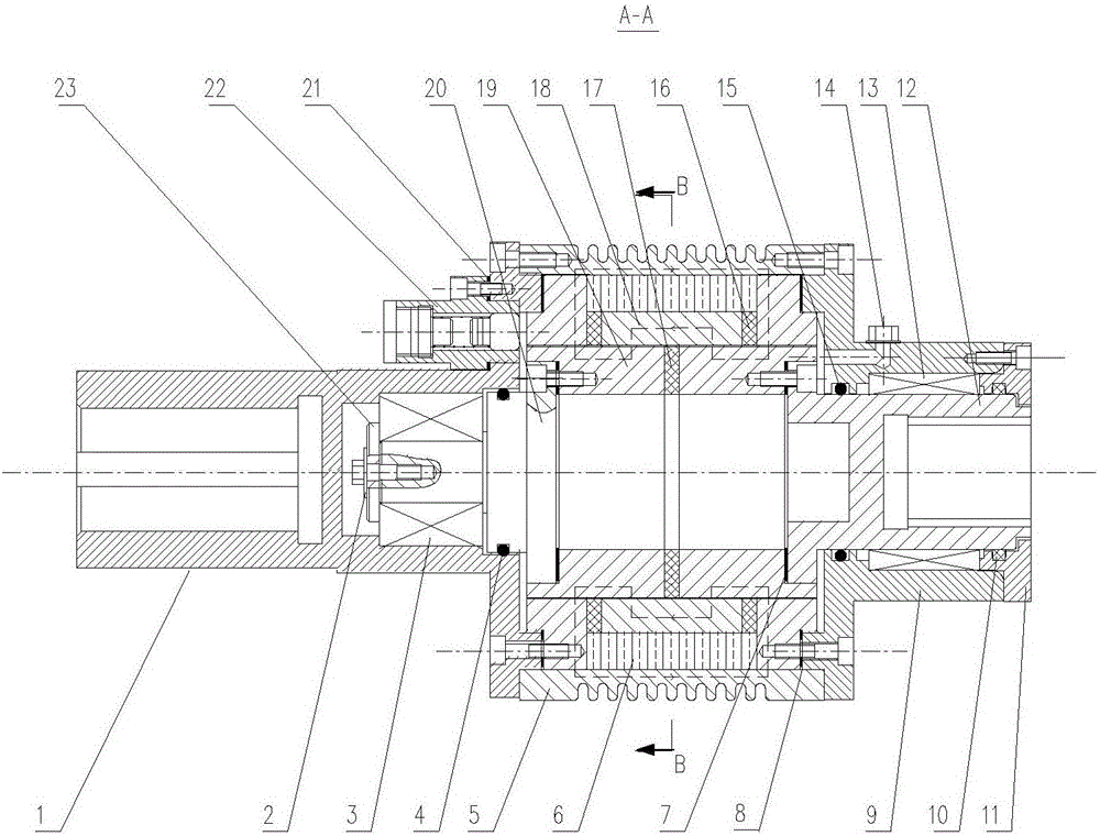
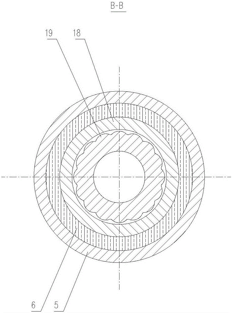
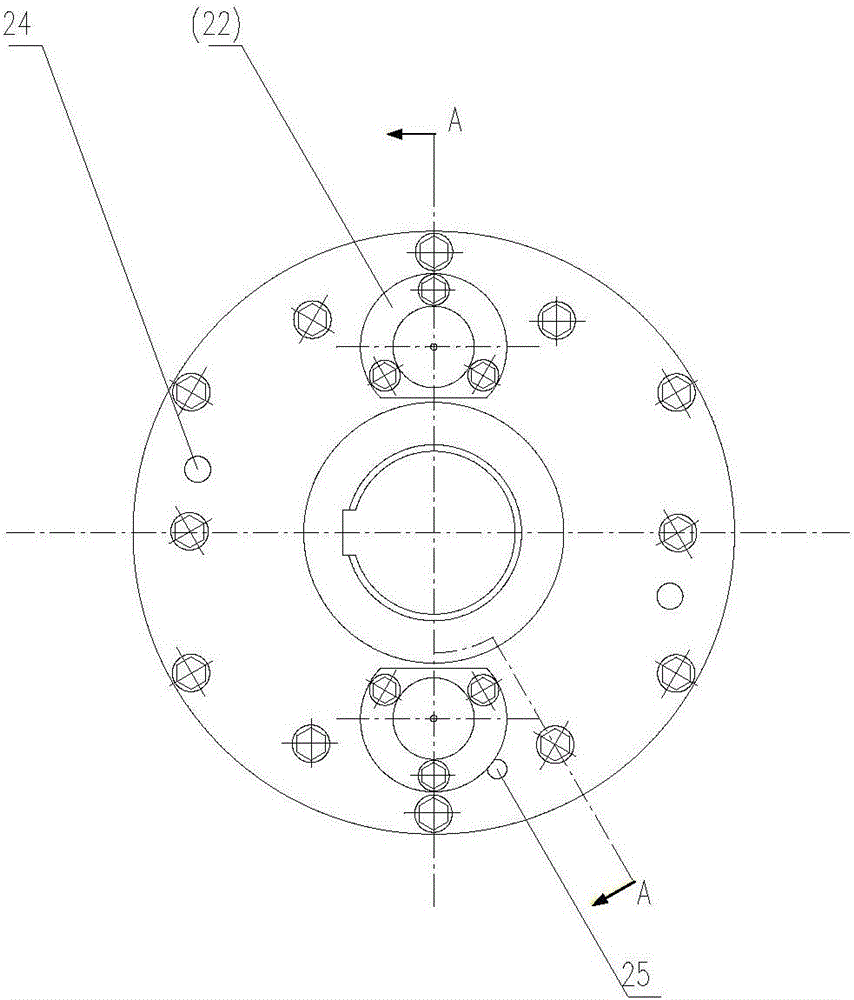
[0022] Such as figure 1 Shown, the present invention is made up of outer rotating part and inner rotating part. External rotating parts include input coupling 1, anti-loosening washer 2, outer sleeve 18, heat sink 5, sealing gasket 8, 21, transparent cover 9, dust seal 10, sealing cover 11, large magnetic isolation ring 16, pressure relief Valve 22, electromagnetic coil 6. The outer sleeve 18 is composed of three annular magnetizers welded with magnetic isolation rings distributed symmetrically along the axial direction on both sides and formed by machining. The annular groove is wound with a multi-turn electromagnetic coil 6 that can generate a magnetic field. The input end The two ends of coupling 1, transparent cover 9 and outer sleeve 18 are respectively connected by magnetically isolated stainless steel screws, cylindrical pins are inserted into the input en...


PUM


Abstract

The invention discloses a compact cycloidal wheel magnetorheological coupling. The compact cycloidal wheel magnetorheological coupling is composed of an outer rotary component and an inner rotary component. An outer sleeve is formed by fixedly connecting a magnetizer and magnetism isolating rings which are symmetrically distributed on the two sides in the axial direction, and a multi-turn electromagnetic coil is wound in an annular groove of the outer sleeve. An outgoing line of the electromagnetic coil and a wiring terminal are guided out from the axial side face of an input-end coupling and connected with a power supply slip ring, and the input end is sleeved with the power supply slip ring. The outer-diameter portion of the outer sleeved is sleeved with cooling fins, and the two ends of the outer sleeve are connected with the input end of the coupling and a transparent cover through magnetism isolating screws. Oil injection plug screws are symmetrically distributed and mounted on the axial outer-diameter portion of the transparent cover. Pressure release valves which are symmetrically distributed are mounted at the input-end coupling in the circumferential direction. An outer cycloidal wheel sleeve is formed by fixedly connecting a cycloidal wheel and an inner magnetism isolating ring and is of a hollow barrel-shaped structure, and the two ends of the outer cycloidal wheel sleeve are connected with a rotary flange and an output-end coupling through magnetism-isolating stainless steel screws correspondingly. The inner rotary component and the outer rotary component are connected through a bearing. The compact cycloidal wheel magnetorheological coupling has the advantages of being compact in structure, low in manufacturing cost, convenient to maintain, and capable of transmitting a large torque.

Description

technical field [0001] The patent of the invention belongs to the field of mechanical transmission and control, and specifically relates to a compact cycloid magneto-rheological coupling. Background technique [0002] Traditional couplings are divided into rigid couplings and flexible couplings. The former has a simple structure, but has high requirements for the stability of the transmission process; the coupling using elastic elements in the latter has certain buffering and vibration reduction functions, but the ability to transmit torque is limited according to the performance of the elastic elements. limits. Couplings that use traditional elastic elements as power transmission and damping media are widely used in the field of vibration damping control, but their control methods have disadvantages such as complex technology and high maintenance costs, and are not suitable for high-speed, heavy-duty transmission control. occasion. [0003] At present, research on magnet...

Claims


Application Information

Patent Timeline
Patent Type & Authority Applications(China)
IPC IPC(8): F16D37/02
CPCF16D37/008F16D37/02F16D2037/001
Inventor 王贡献张隆李春辉孙晖
Owner WUHAN UNIV OF TECH
Why Eureka
Try Eureka