Bio-signal measuring device

a biosignal and measuring device technology, applied in the field of biosignal measuring devices, can solve the problems flexibility, and weight, and achieve the effect of reducing the size, weight and thickness of the measuring instrument, and ensuring the accuracy of measurement results

Active Publication Date: 2019-11-28
TECHNO COMMONS
View PDF3 Cites 4 Cited by
  • Summary
  • Abstract
  • Description
  • Claims
  • Application Information

AI Technical Summary

Benefits of technology

[0044]According to the first aspect of the present invention, the electrode for originally detecting a bio-signal is used as a charging terminal, whereby it is not necessary to provide a dedicated charging terminal such as an SD terminal, and the configuration of the bio-signal measuring instrument is simplified, and thus the size, the weight, and the thickness can be further reduced, and sufficient waterproof measures can be taken.
[0045]Further, a configuration, in which the bio-signal measuring device includes the first substrate in which the bio-signal processing circuit is mounted on the surface on one side thereof, and the second substrate in which the battery and the charging circuit for the battery are mounted on the surface on one side thereof, and the electrode is provided on the side of the surface on the other side of each of the first substrate and the second substrate, and the first substrate and the second substrate are connected through the low-bending rigidity part having conductive wiring, is adopted, whereby it is possible to provide a small and thin bio-signal measuring instrument which can be mounted on a living body almost without discomfort.
[0046]According to the second aspect of the present invention, the biological data stored in the memory of the bio-signal measuring instrument (sensor chip) can be transmitted to the external equipment through the power feeder even during the charging of the battery, and on the contrary, a predetermined command can be provided from the external equipment to the sensor chip through the power feeder or firmware or the like can be rewritten, and therefore, it is possible to collect effective bio-signals in order to analyze data.
[0047]According to the third aspect of the present invention, only when the bio-signal measuring instrument (wearable biosensor) is mounted to the human body, the power source start switch is turned on, so that a power source is supplied from the battery to the bio-signal processing circuit, and otherwise, the power source start switch is turned off. Therefore, battery consumption can be reduced as much as possible. Further, the power source switch is composed of a comparator and a resistance element and is not a mechanical power source switch, and therefore, it is possible to enhance waterproofness.

Problems solved by technology

However, in order to provide a durable charging terminal on a small circuit substrate manufactured for a wearable instrument, it is necessary to increase the strength of the circuit substrate, and this becomes a hindrance to a reduction in size, a reduction in weight, a reduction in thickness, or flexibility.
However, in order to provide waterproof measures to the charging terminal such as an SD terminal, a considerable devisal is required, and a structure becomes complicated, which causes an increase in cost.
However, there is a problem such as a narrow communication range or severe battery consumption.
However, it is inefficient and undesirable to separately perform the collection of the bio-signal and the charging of the secondary battery.

Method used


Image

  • Bio-signal measuring device
  • Bio-signal measuring device
  • Bio-signal measuring device

Examples


first embodiment

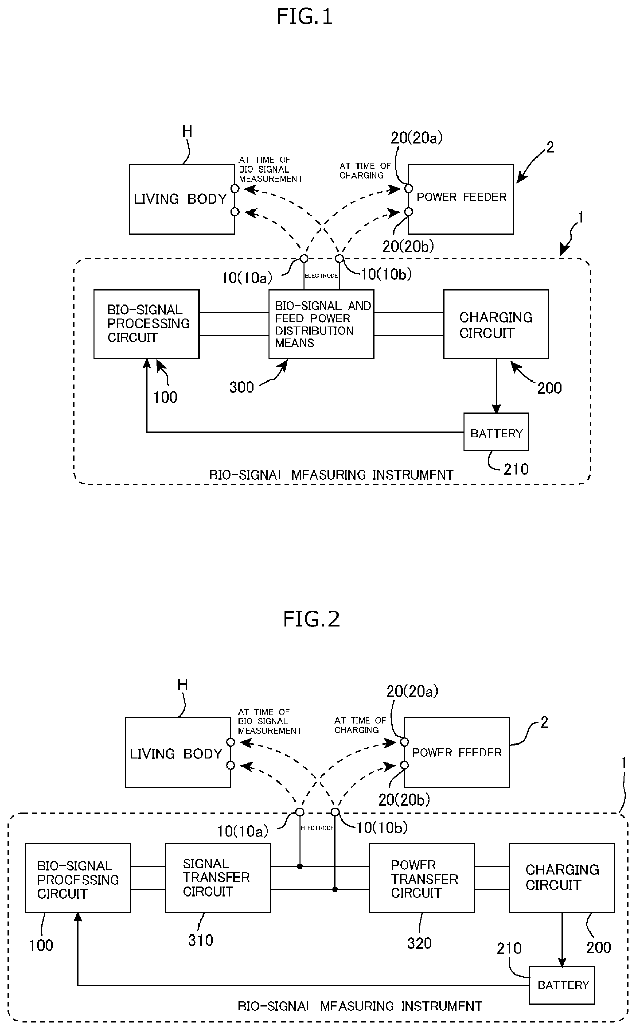
[0073]As shown in FIG. 1, a bio-signal measuring device according to this embodiment (a first embodiment) includes a bio-signal measuring instrument 1 as a wearable biosensor (sensor chip) and a power feeder (a charger) 2 which feeds charging power to a secondary battery 210 built in the bio-signal measuring instrument 1.

[0074]The bio-signal measuring instrument 1 includes, as a basic configuration, a pair of electrodes 10a and 10b, a bio-signal processing circuit 100, the secondary battery 210 as an internal power source, a charging circuit 200 for charging the secondary battery 210, and bio-signal and feed power distribution means 300. The bio-signal processing circuit 100 and the charging circuit 200 are switchably connected to the electrodes 10a and 10b through the bio-signal and feed power distribution means 300.

[0075]The electrodes 10a and 10b are brought into contact with a living body (human body) H at the time of bio-signal measurement and brought into contact with power fe...

fifth embodiment

[0145]As another embodiment (the present invention) of the communication function with the power feeder 2, as shown in FIG. 15, an aspect including a wakeup circuit 131 as connection detection means, a switch (SW) 132 for modulation, an ADC 133, an error correction decoding circuit 134a, an error correction coding circuit 134b, and a communication control unit 135 is also included in the present invention.

[0146]The wakeup circuit 131 detects the feed power (charging power) to determine that this device (the bio-signal measuring instrument 1) is set to the power feeder 2, and causes the communication function to be in an operating state.

[0147]The switch 132 for modulation changes the impedance between the differentials in order to modulate the feed power. An external transistor with high withstand voltage can be placed.

[0148]The ADC (a comparator is also acceptable) 133 converts the modulation of the feed power into a binary or multiple values. A protective resistor or a protective d...


PUM


Abstract

A secondary battery built in a bio-signal measuring instrument (a wearable biosensor) is charged without using a dedicated charging terminal. A bio-signal measuring device includes: a battery as an internal power source and a charging circuit for the battery; electrodes which are brought into contact with the skin surface of the human body at the time of bio-signal measurement and are connected to a predetermined power feeder at the time of charging of the battery; a bio-signal processing circuit which processes bio-signals detected at the electrodes in a predetermined manner; and a bio-signal and feed power distribution device, in which the bio-signal processing circuit and the charging circuit are switchably connected to the electrodes through the bio-signal and feed power distribution device, and at the time of the charging of the battery, the electrodes are used as charging terminals.

Description

TECHNICAL FIELD[0001]The present invention relates to a bio-signal measuring device and more specifically, to a bio-signal measuring device which includes a bio-signal measuring instrument (wearable biosensor) which is used in a state of being stuck to a living body (human body), like a sticking plaster, and a power feeder which charges a built-in battery.BACKGROUND ART[0002]In a wearable type bio-signal measuring instrument, in addition to a bio-signal measuring and processing unit that measures and processes, for example, an electrocardiographic signal, a myoelectric signal, an electroencephalographic signal, or the like, a battery as an internal power source that supplies a power source to the bio-signal measuring and processing unit is built in.[0003]Usually, a secondary battery such as a lithium ion battery is used for the battery, and therefore, an SD terminal or a dedicated charging terminal for charging the secondary battery is provided, and when charging the secondary batte...

Claims


Application Information

Patent Timeline
Patent Type & Authority Applications(United States)
IPC IPC(8): A61B5/0428A61B5/0476H02J7/00A61B5/308
CPCA61B5/0476H02J7/0052A61B5/6802H02J7/0047A61B5/04288A61B5/318A61B5/352A61B5/353A61B5/355A61B5/389A61B5/369A61B5/0531A61B5/725H01H36/0006H02J7/0031H02J7/0045H02J7/0063A61B2560/0214H02J7/0068H02J7/00034H02J2310/23H02J7/0042A61B5/304A61B2560/0209A61B5/30A61B5/746A61B5/0002H02J7/00
Inventor TANAKA, AKIOCHAN, CHUNKITHIGUCHI, KOHEIMAENAKA, KAZUSUKE
Owner TECHNO COMMONS
Why Eureka
Try Eureka