
Cooling fin pipe smoker

a technology for smoking fin pipes and tobacco pipes, applied in tobacco pipes, applications, tobacco, etc., can solve the problems of unburned tobacco, unburned tobacco, and unburned tobacco

Inactive Publication Date: 2010-09-02
BORDEN KOALA T
View PDF3 Cites 22 Cited by
  • Summary
  • Abstract
  • Description
  • Claims
  • Application Information

AI Technical Summary

Benefits of technology

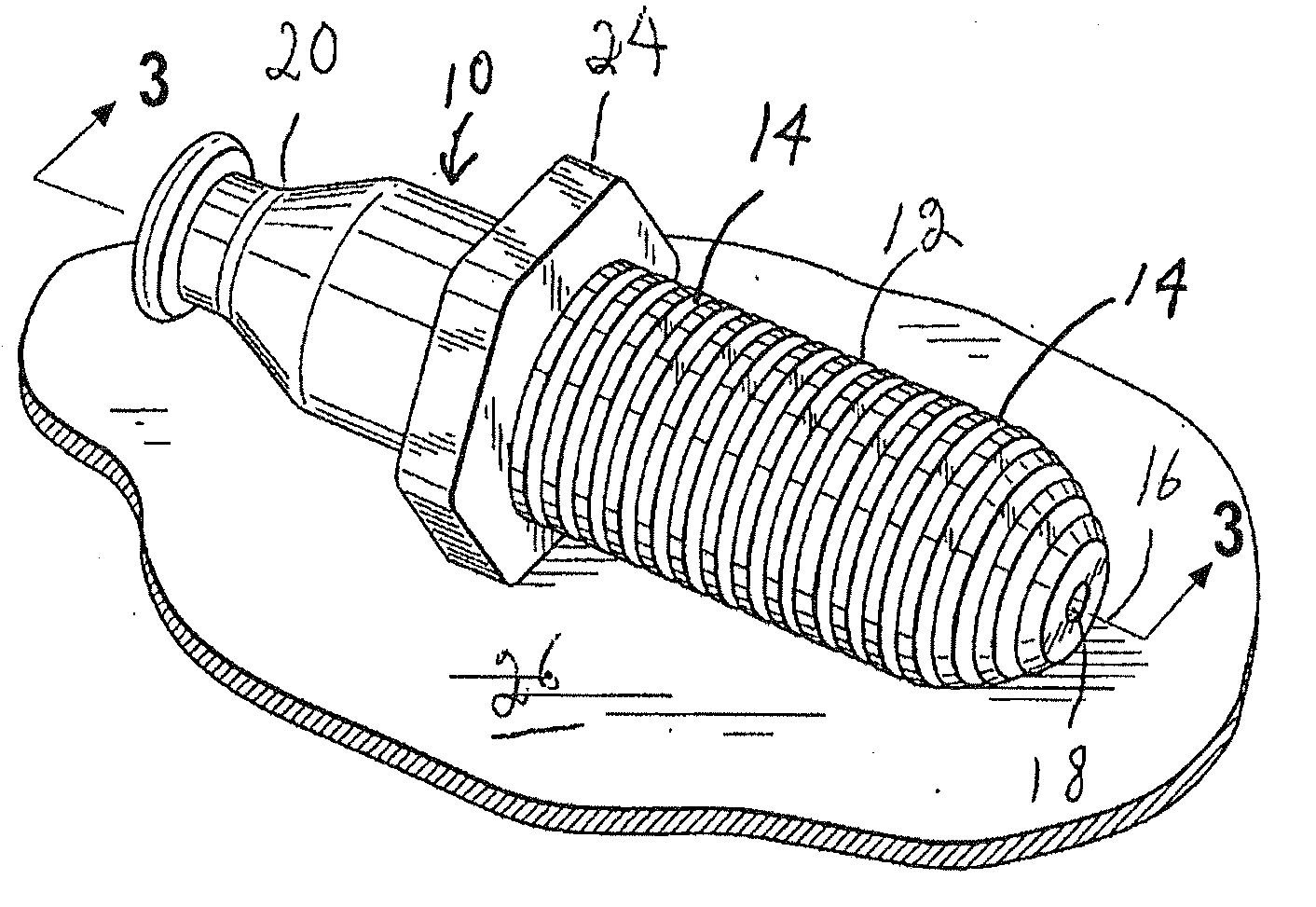
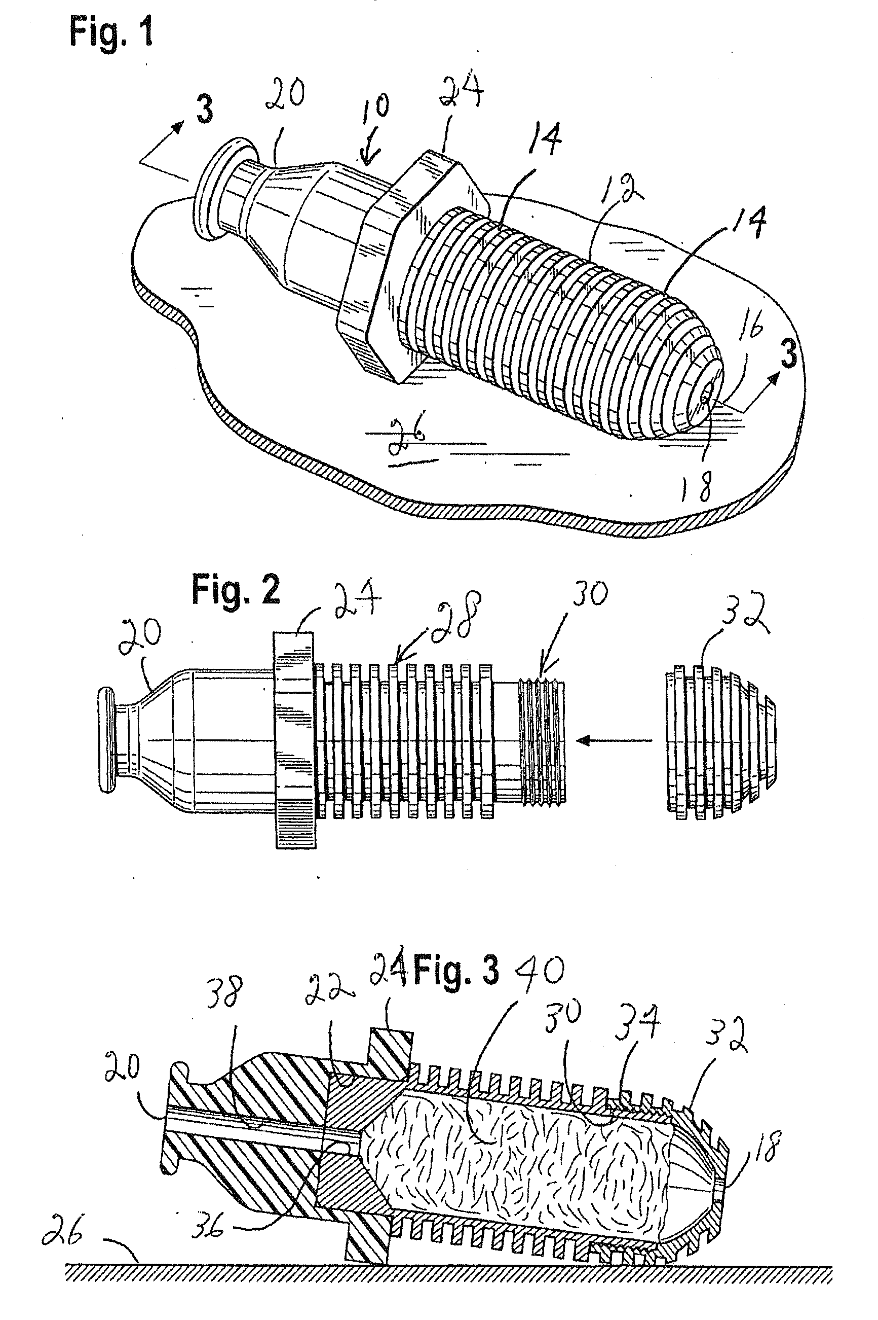
[0005]A pipe smoker with cooling fins and an octagonal mouthpiece for the pipe smoker is described herein. In one embodiment of a cooling fin pipe smoker includes a generally elongated tubular housing with a first opening of a predetermined size at a top end in align with the longitudinal axis of the housing and a second opening of a predetermined size at an opposing bottom end in align with the longitudinal axis of the housing to draw out the tobacco smoke when the pipe is lit. The housing includes two parts, an internal bowl for receiving the tobacco and a cap mechanically attached to the bowl to hold the tobacco within the bowl in use. The two part tubular housing formed by the bowl and cap include external parallel fins of a predetermined thickness and spaced apart a generally uniform and predetermined distance from one another on the exterior of the housing perpendicular to the longitudinal axis of the housing when the cap is mechanically attached to the bowl. The fins transfer the heat from within the joined parts of the bowl and cap of the housing when assembled so that the heat is radiated outwardly from the lit tobacco within the pipe to provide a cooling effect when smoking the tobacco within the cooling fin pipe smoker.

Problems solved by technology

Depending upon the design of the pipe, it often is a problem keeping the pipe lit due to wind or drafts with the large open bowls on most pipes.
However, in reality, the tamper often misses areas within the bowl causing uneven burning of the tobacco with a flame that often goes out during the smoking process.
Burn outs within the open pipe bowls results in unburned tobacco typically being mixed in with new tobacco before lighting the pipe again.
Moreover, the pipe might incur hot spots within the steady burning of the tobacco within the open pipe bowl.

Method used


Image

  • Cooling fin pipe smoker
  • Cooling fin pipe smoker

Examples


Embodiment Construction

[0009]While the invention is described herein with the reference to a number of embodiments and methods of use, it should be understood that the invention should not be limited to such embodiments or uses. The description of the embodiments and uses herein are illustrative only and should not limit the scope of the invention as claimed. Embodiments are presented in the figures, which are not drawn to scale and in which like components are numbered alike.

[0010]Apparatus for tobacco smoking within a pipe includes exterior males threads on the outer surface of the bowl end joining the cap and corresponding matching female threads on the interior of the cap providing a mechanical locking of the cap to the bowl once tobacco is inserted within the bowl to fixedly join the bowl and cap together for use. The cooling fins are spaced apart in a parallel relationship with respect to each other and extend outwardly from the outer surface of the bowl and cap a predetermined distance that is perp...


PUM


Abstract

A cooling find smoker pipe having a plurality of parallel fins spaced apart a predetermined distance on the generally tubular housing of the pipe to cool the tobacco smoke from the pipe when the end user takes a drag on the pipe mouthpiece attached to the housing. The housing comprises a two piece construction of a cap and a tobacco bowl screwed together to form the chamber to fill with tobacco wherein the male threads are located on the exterior of the bowl and the corresponding female threads are located within the cap.

Description

CROSS-REFERENCE TO RELATED APPLICATIONS[0001]This application claims benefit from U.S. Provisional Patent Application No. 61 / 156,853 entitled “COOLING FIN PIPE SMOKER” filed on Mar. 2, 2009.FIELD OF THE INVENTION[0002]The present invention relates generally to apparatus for smoking, and more particularly relates to apparatus for smoking tobacco and the like through a pipe smoker.BACKGROUND OF THE INVENTION[0003]Due to the inherent problems with cigarettes, many tobacco smokers are turning to pipe smoking to avoid the messy rolling of their own tobacco in paper to form the cigarette if they are interested in trying and using different quality tobaccos. There are various pipes made of wood, plastic and other materials having the traditional open bowl with a tube attached thereto to smoke the tobacco inserted into the bowl. Depending upon the design of the pipe, it often is a problem keeping the pipe lit due to wind or drafts with the large open bowls on most pipes.[0004]Also, the unif...

Claims


Application Information

Patent Timeline
IPC IPC(8): A24F1/32
CPCA24F1/02
Inventor BORDEN, TEDDY H.
Owner BORDEN KOALA T
Learn More