DC power supply device with constant power output level

Inactive Publication Date: 2003-10-02
SHINDENGEN ELECTRIC MFG CO LTD
View PDF1 Cites 147 Cited by
  • Summary
  • Abstract
  • Description
  • Claims
  • Application Information

AI Technical Summary

Problems solved by technology

Therefore, the transformer is poorly exploited as it is used at the output level of 10 kW although it has a capacity of 20 kW.
As pointed out above, the conventional control method is accompanied by disadvantages including that the transformer is poorly exploited and hence the use of a large filter is required and that the effective current o

Method used


Image

  • DC power supply device with constant power output level
  • DC power supply device with constant power output level
  • DC power supply device with constant power output level

Examples


Embodiment Construction

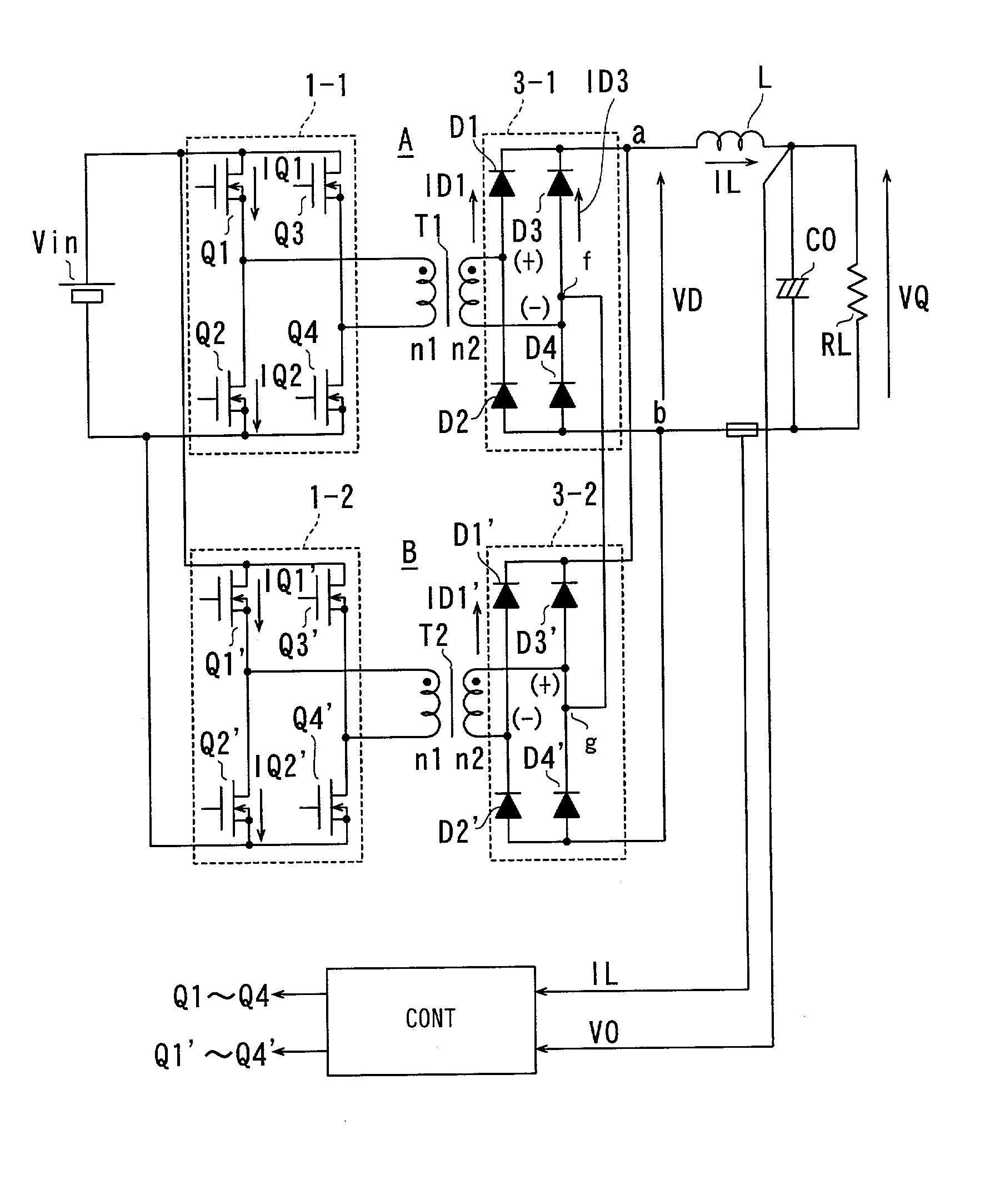
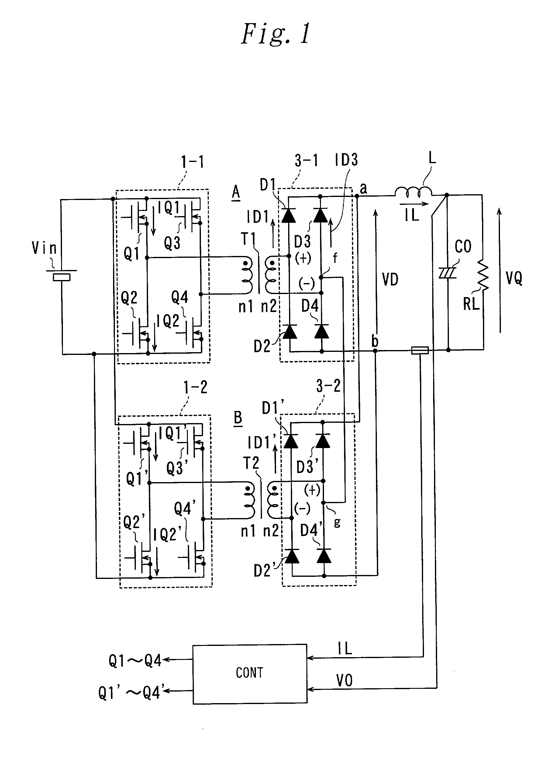
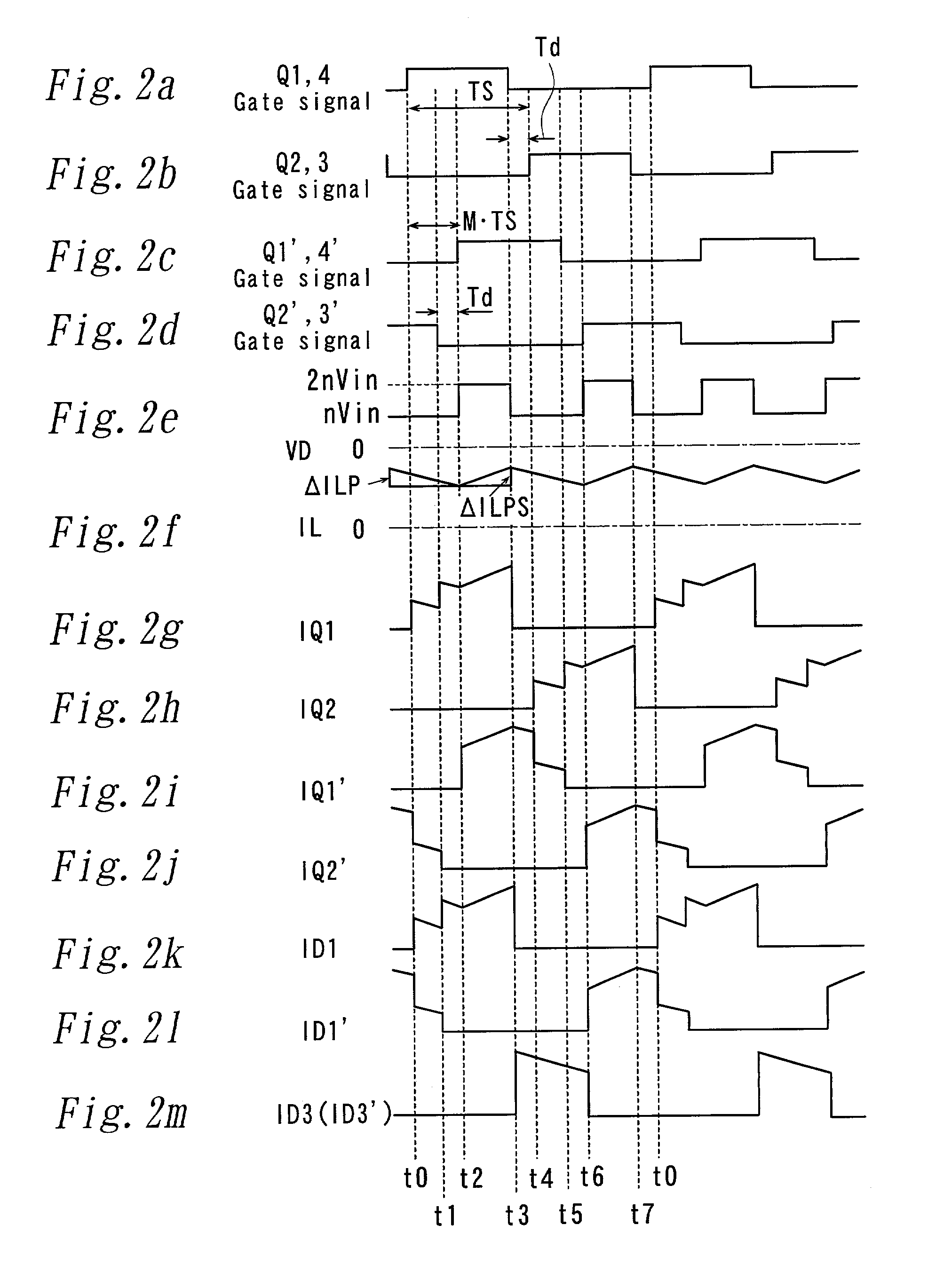
[0094] FIG. 1 is a circuit diagram of an example of the invention. Referring to FIG. 1, reference symbol 1-1 denotes a full-bridge type switching changer comprising switching elements Q1 through Q4. T1 denotes a transformer in which the primary winding n1 and the secondary winding n2 are made to show a turn ratio of 1:n. Reference symbol 3-1 denotes a rectifying circuit comprising rectifying diodes D1 through D4. L denotes an output choke coil and Co denotes a smoothing capacitor, while RL denotes a load. A DC power supply device A is formed by these components.

[0095] Another DC power supply device B similar to the DC power supply device A is formed also by a switching changer 1-2, an output transformer T2 and a rectifying circuit 3-2. The terminals a, b of the power supply devices A, B are connected in parallel. The (-) terminal (f), which is the AC input terminal of the rectifying circuit 3-1, and the (+) terminal (g) of the rectifying circuit 3-2 are commonly connected. In FIG. 1...


PUM


Abstract

A DC power supply device includes transformers that operate with an enhanced efficiency and can reduce the factors that generate ripples in the output voltage to make it possible to downsize the transformers and the smoothing filters of the device, reduce the loss attributable to the switching elements during its constant power output operation and also downsize the heat sink fins so that the overall dimensions of the power supply device may be reduced. The DC power supply device also comprises a pair of switching changers, two output transformers and two rectifying/smoothing sections for rectifying the respective outputs of the switching changers. Each of the two switching changers has the same switching cycle period and the striking phases of the switching elements of one of the switching changers and those of the switching elements of the other switching changer are made variable. Then, a constant power output level is achieved by utilizing the difference of the striking phases of the two switching changers in order to isolate the switching changers from each other for operation and connect them in series or in parallel for operation.

Description

[0001] 1. Field of the Invention[0002] This invention relate to a switching power supply device. More particularly, it relates to a DC power supply device with a constant power output level and output power control of such a device.[0003] 2. Description of the Related Art[0004] FIG. 19 of the accompanying drawings is a schematic circuit diagram of a switching power supply device to be typically used for a film forming device. In FIG. 19, reference symbols Q1 through Q4 denote respectively switching elements, which form a full-bridge; and reference symbol T1 denotes a transformer, while D1 through D4 respectively denotes rectifier diodes for the output of the transformer; and L denotes an output choke coil. Additionally, reference symbols Co, R, Vin, n1, n2 and VQ respectively denote a smoothing capacitor, a load, an input voltage source, a primary winding, a secondary winding and output voltage.[0005] Constant power control is required for controlling a film forming device. Therefor...

Claims


Application Information

Patent Timeline
IPC IPC(8): H02M3/28
CPCH02M2007/53878H02M3/285H02M7/53878
Inventor MATSUDA, YOSHIAKIOFUJI, SHINYA
Owner SHINDENGEN ELECTRIC MFG CO LTD
Why Eureka
Try Eureka