Display Apparatus And Display System

Inactive Publication Date: 2010-09-02
SANYO ELECTRIC CO LTD
View PDF6 Cites 56 Cited by
  • Summary
  • Abstract
  • Description
  • Claims
  • Application Information

AI Technical Summary

Benefits of technology

[0008]A display system of the present invention comprises: a display apparatus; a frame; an engaging component (81) arranged on the display; an engaged component (82) engages to the engaging component (81) an

Problems solved by technology

However, in the outdoors, vibrations caused by vehicles p

Method used


Image

  • Display Apparatus And Display System
  • Display Apparatus And Display System
  • Display Apparatus And Display System

Examples


Embodiment Construction

[0050]The present invention embodied in a display apparatus or display system will be specifically described below with the reference to the drawings.

[0051]1. Overview of the Display System

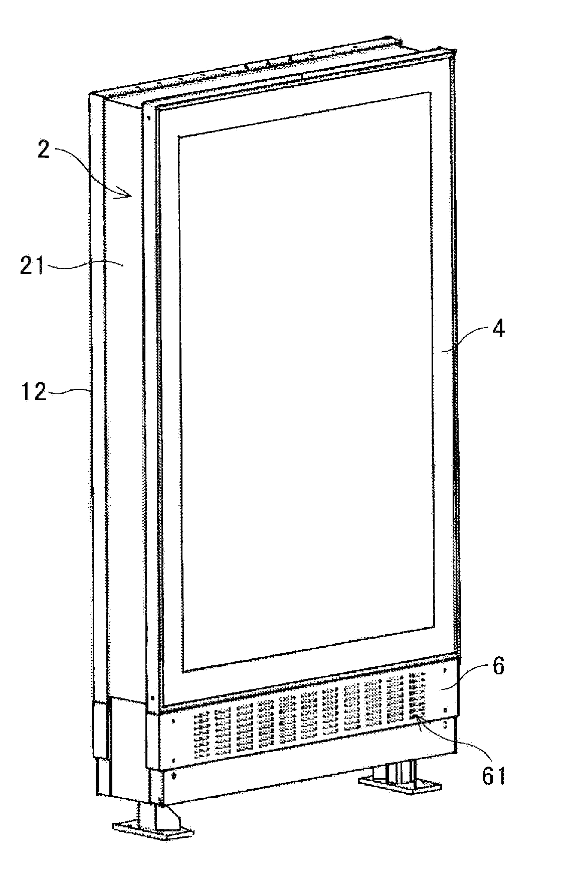
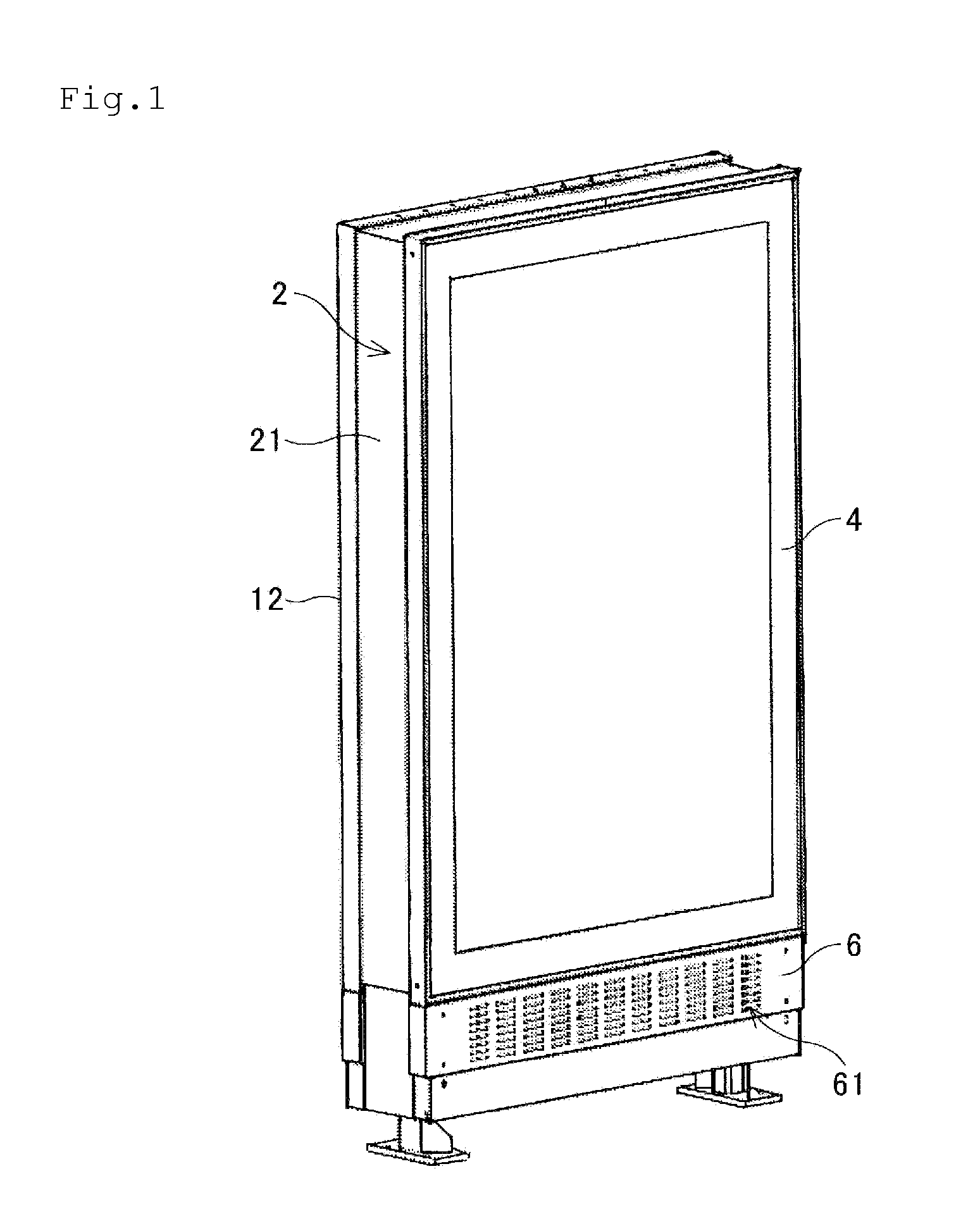
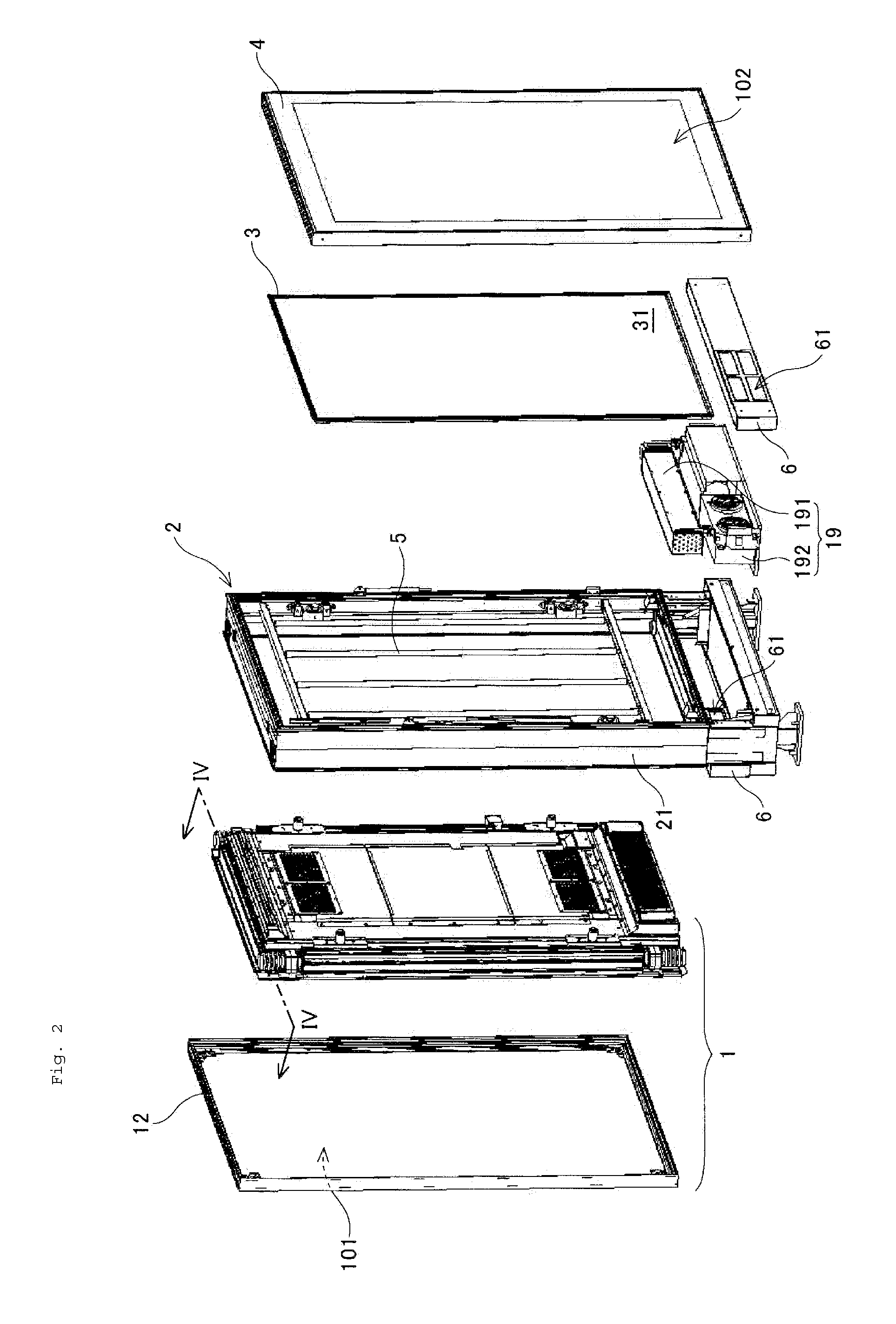
[0052]As shown in FIG. 1 the display system has a flat rectangular appearance, and as shown in FIG. 2, it includes a display apparatus 1, support stand 2, backboard 3, cover 4, fluorescent light fittings 5, and pair of aeration plates 6, 6. The display apparatus 1 displays an image on the surface 101 of the display system, and has a liquid crystal display 10 as shown in FIG. 5. The detail of the display apparatus 1 is explained below in section 2 entitled “A display apparatus”.

[0053]The support stand 2 supports the display apparatus 1 and the backboard 3, and a frame part 21 for attaching the display apparatus 1 and the backboard 3 is formed. The frame part 21 has a structure that can contain the display apparatus 1 and the backboard 3. The structure for attaching the display apparatus 1 to the su...


PUM


Abstract

A display system comprising: a display apparatus; a frame; an engaging component (81) arranged on the display; an engaged component (82) engages to the engaging component (81) and connected to the frame via an elastic component (84); a preventing component (85) fixed to the engaged component (82), wherein the prevention component (85) prevents the display apparatus from falling ahead.

Description

[0001]This application claims priority under 35 U.S.C. §119 from Japanese patent application numbers 2009-020349, 2009-020350, 2009-020351, 2009-020352, and 2009-020353, all of which are hereby incorporated by reference herein.BACKGROUND OF THE INVENTION[0002]1. Field of the Invention[0003]The present invention relates to a display system, especially, a display system for installation outdoors.[0004]2. Description of Related Art[0005]Conventionally, plane surface type displays, such as liquid crystal displays (LCDs), are widely used.[0006]Recently, it has been desired to place liquid crystal displays permanently outdoors, because the thickness of the displays are small and can display high resolution pictures. Since the thickness of the LCD display is small, it can be installed on an outer wall of a building, or in narrow places such as bus stop shelters, etc. Moreover, because the resolution of a LCD display is high, it can display a clear picture even if the screen size is small.[...

Claims


Application Information

Patent Timeline
IPC IPC(8): H04N5/64
CPCH05K5/02H05K9/0096H05K7/20972
Inventor NAKAMICHI, MASAYATAKAHASHI, SHOHEITAKE, NOBUYUKI
Owner SANYO ELECTRIC CO LTD
Why Eureka
Try Eureka