
Multifaceted implantable syncope monitor - mism

a monitoring device and implantable technology, applied in the field of implantable monitoring devices, can solve the problems of ineffective treatment, inability to measure sufficient patient physiologic indicators, and general inability to determine devices,

Inactive Publication Date: 2010-09-09
PACESETTER INC
View PDF19 Cites 59 Cited by
  • Summary
  • Abstract
  • Description
  • Claims
  • Application Information

AI Technical Summary

Benefits of technology

[0009]In one further exemplary embodiment, the implantable syncope monitor is further equipped with a photoplethsymography (PPG) monitor that is capable of obtaining data indicative of the patient's hemodynamic and respiratory performance. The monitor is thus simultaneously receiving signals indicative of the patient's musculature contractions, the heart function and other hemodynamic and respiratory functions. As such, the monitor is better capable of capturing data indicative of the likely cause of syncope within the patient and is further better capable of illustrating the temporal relationship.

Problems solved by technology

One difficulty that occurs with patients who suffer from syncope is that the cause of the syncope is often misdiagnosed and, thus, not effectively treated.
One cause of the misdiagnosis of the cause of syncope and syncope-related events is that the implanted monitoring devices currently employed are not capable of measuring sufficient patient physiologic indicators that would allow for a more accurate diagnosis.
While these monitoring devices are effective at detecting physiologic conditions of the heart that could cause syncope related events, these devices are generally not capable of determining if the syncope related event is caused by epileptic sources or not.
This placement limits the ability of the device to sense physiologic characteristics of the muscles that may be indicative of a seizure related syncope.
Implanted cardiac-based monitoring devices also often lack the ability to sense photoplethysmography (PPG) data which limits the functionality of the monitoring device.
Further, syncope monitoring systems are often not set up to capture a wide variety of signals simultaneously and are thus less capable of ascertaining temporal indications indicative of different sources of syncope-related events.

Method used


Image

  • Multifaceted implantable syncope monitor - mism
  • Multifaceted implantable syncope monitor - mism
  • Multifaceted implantable syncope monitor - mism

Examples


Embodiment Construction

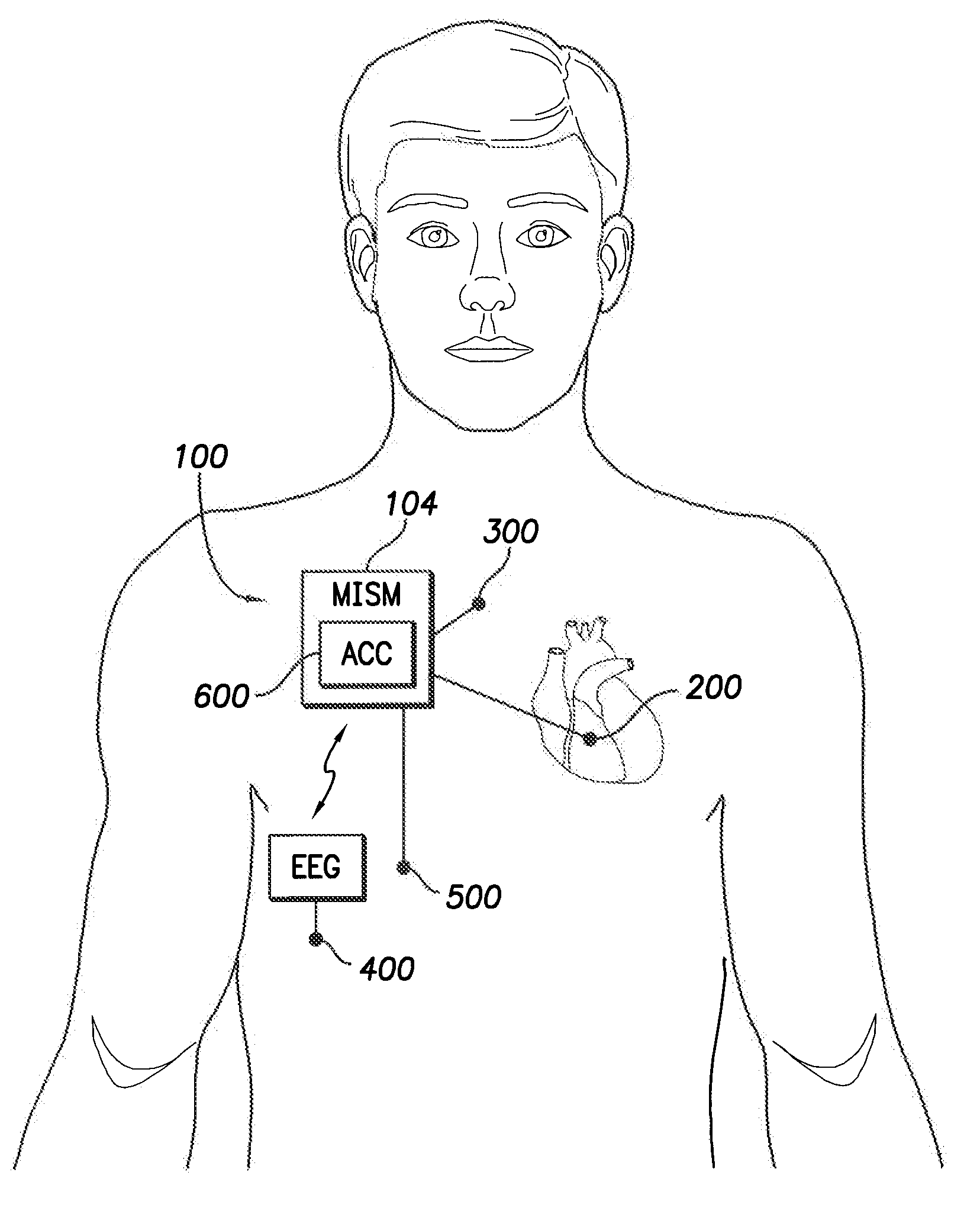
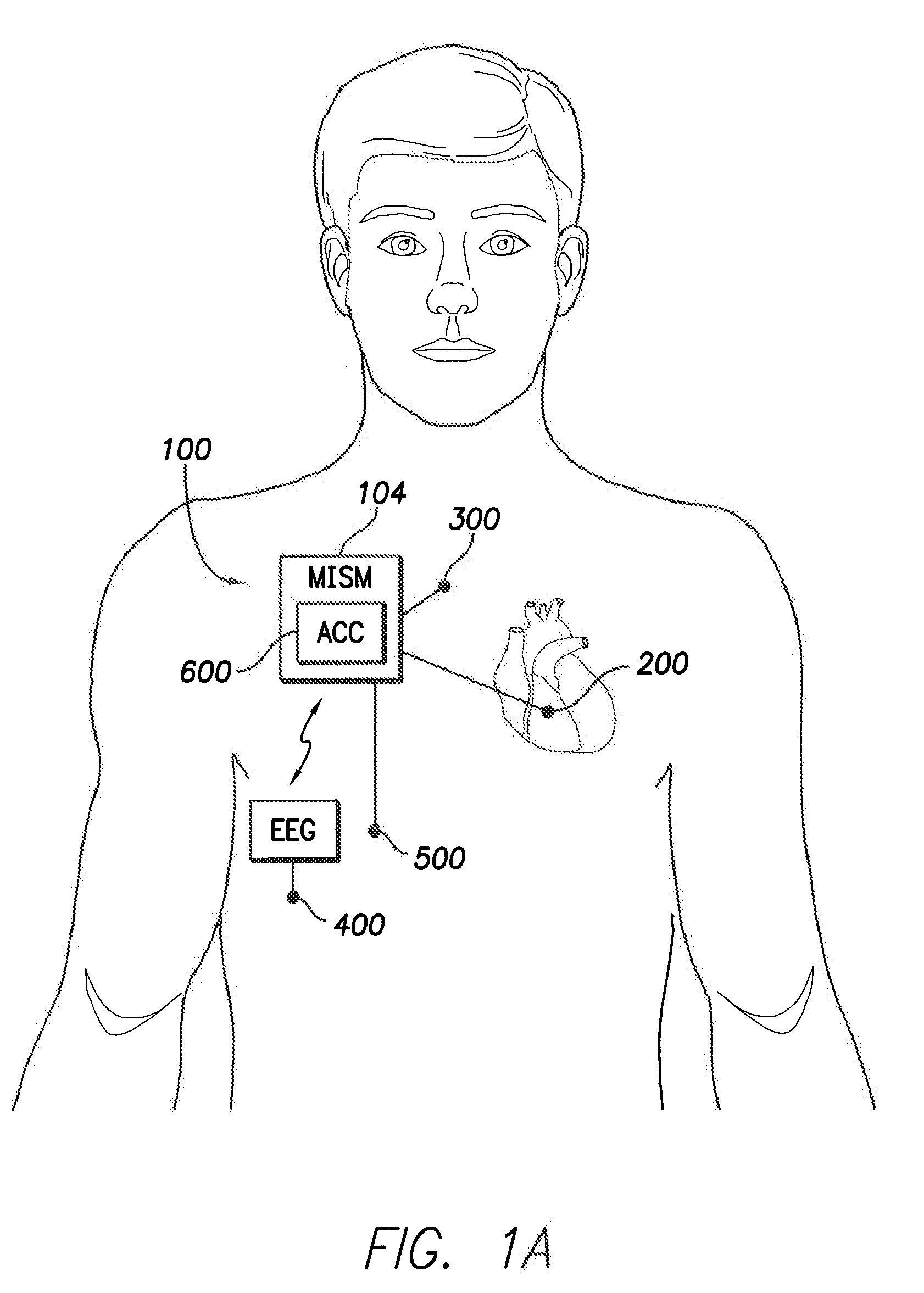
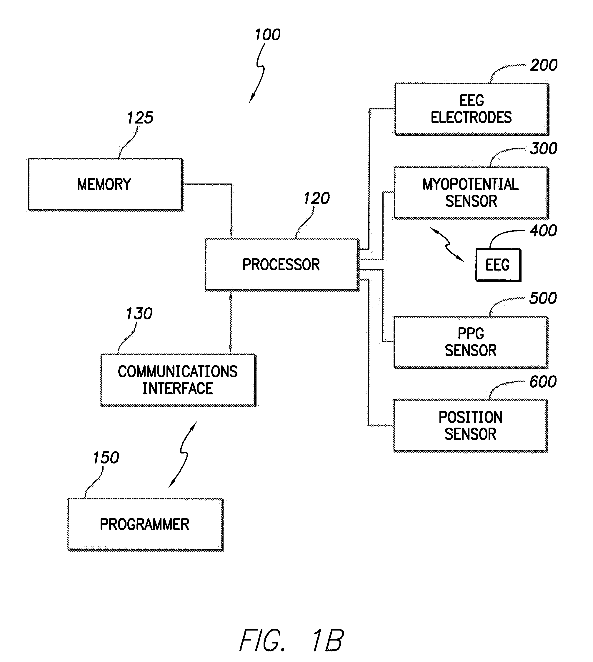
[0018]Reference will now be made to the drawings wherein like numerals refer to like parts throughout. Referring initially to FIGS. 1A and 1B, one embodiment of a multi-faceted implantable syncope monitor (MISM) 100 is shown. In this implementation, the MISM 100 is capable of monitoring multiple different types or channels of physiologic data about the patient, including heart related data, hemodynamic and respiratory related data and myopotential related data, simultaneously in order to be able to capture sufficient data to enable a more accurate diagnosis of the cause of syncope related events in a patient 102. Referring initially to FIG. 1A, the MISM 100 is shown implanted within the body of a patient. The actual implantation site can vary, depending upon circumstances, but one potentially efficacious implantation site is adjacent the pectoral muscle of the patient in a manner similar to the manner in which implantable cardiac stimulation devices are implanted. Indeed, the MISM 1...


PUM


Abstract

A multi-channel implantable syncope monitor that monitors ECG data, myopotential data, EEG data, photoplethysmography (PPG) data, and position sensor data is used to capture physiologic data about a patient who is experiencing a syncopal event. The timing of the events within the simultaneously captured physiologic data can then be used to more accurately determine potential sources of origin of the syncopal event.

Description

FIELD OF THE INVENTION[0001]The present invention relates to implantable monitoring devices and, in particular, concerns an implantable syncope monitoring device and methods of monitoring a plurality of different patient characteristics to determine possible causes or sources of syncope.BACKGROUND OF THE INVENTION[0002]Syncope of unknown etiology is very common. A wide variety of different physiologic conditions can lead to syncope or fainting. These conditions can include orthostatic hypotension, vasovagal episodes, arrhythmic events that impede blood flow and cataplexy.[0003]One difficulty that occurs with patients who suffer from syncope is that the cause of the syncope is often misdiagnosed and, thus, not effectively treated. For example, patients who suffer vasovagal episodes are often diagnosed as having epileptic episodes and are treated accordingly. Similarly, people suffering from epileptic episodes are often misdiagnosed as having vasovagal episodes.[0004]One cause of the ...

Claims


Application Information

Patent Timeline
IPC IPC(8): A61B5/00
CPCA61B5/021A61B5/0402A61B5/0476A61B5/0488A61B5/4094A61B5/1116A61B5/1118A61B5/145A61B5/0816A61B5/318A61B5/369A61B5/389
Inventor SCHECTER, STUART O.
Owner PACESETTER INC
Learn More