
Head and Neck Restraint System

a head and neck restraint and head and neck technology, applied in helmets, garments, clothing, etc., can solve the problems of not adequately protecting the neck, the helmet does not limit the neck motion of the driver, etc., and achieves the effect of limiting rearward movement and preventing forward movemen

Inactive Publication Date: 2010-09-16
MOTHAFFAR HUSSAIN
View PDF22 Cites 19 Cited by
  • Summary
  • Abstract
  • Description
  • Claims
  • Application Information

AI Technical Summary

Benefits of technology

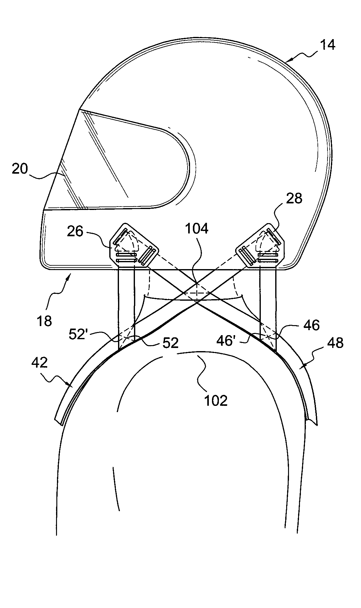
[0011]In addition, the system includes means for releasably securing the plurality of straps to the arch-shaped shoulder member and wherein the plurality of straps form an X-pattern configuration on a right side and a left side of the individual below the helmet. Finally, the system includes a pair of adjustable upwardly extending restraint members that extend upwardly behind the head of an individual and a pair of tethers or straps connecting the helmet to the upwardly extending restraint members to thereby prevent excessive forward movement of the head in the event of an accident. The upwardly extending restraint members also prevent or limit rearward movement of the head during an accident.
[0014]A pair of adjustable upwardly extending restraint members that extend upwardly behind the head of the individual and third and fourth flexible connecting means with one of said flexible connecting means connecting an upper side of said head shell to one of said upwardly extending restraint members and the other of said third and fourth flexible connecting means connecting an upward side of the other side of said head shell to the other of said upwardly extending restraint members whereby the upwardly extending restraint member prevents forward movement of the individual's head as a result of a crash and wherein the upwardly extending restraint member also limit rearward movement of the individual's head to prevent whiplash or other injury.

Problems solved by technology

However, the use of a helmet does not limit the range of motion of the driver's neck and does not adequately protect the neck in the event of an accident particularly one of high speed.

Method used


Image

  • Head and Neck Restraint System
  • Head and Neck Restraint System
  • Head and Neck Restraint System

Examples


Embodiment Construction

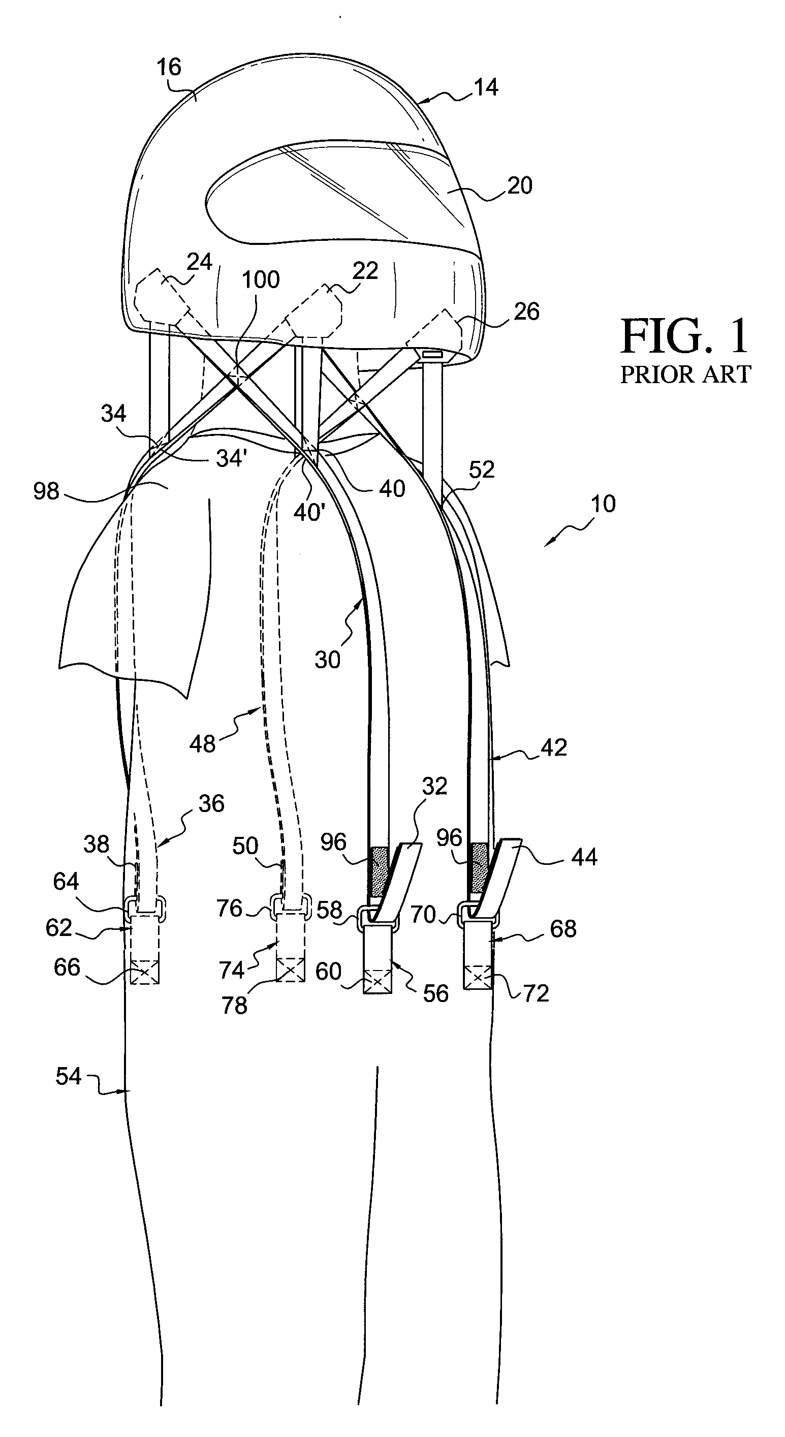
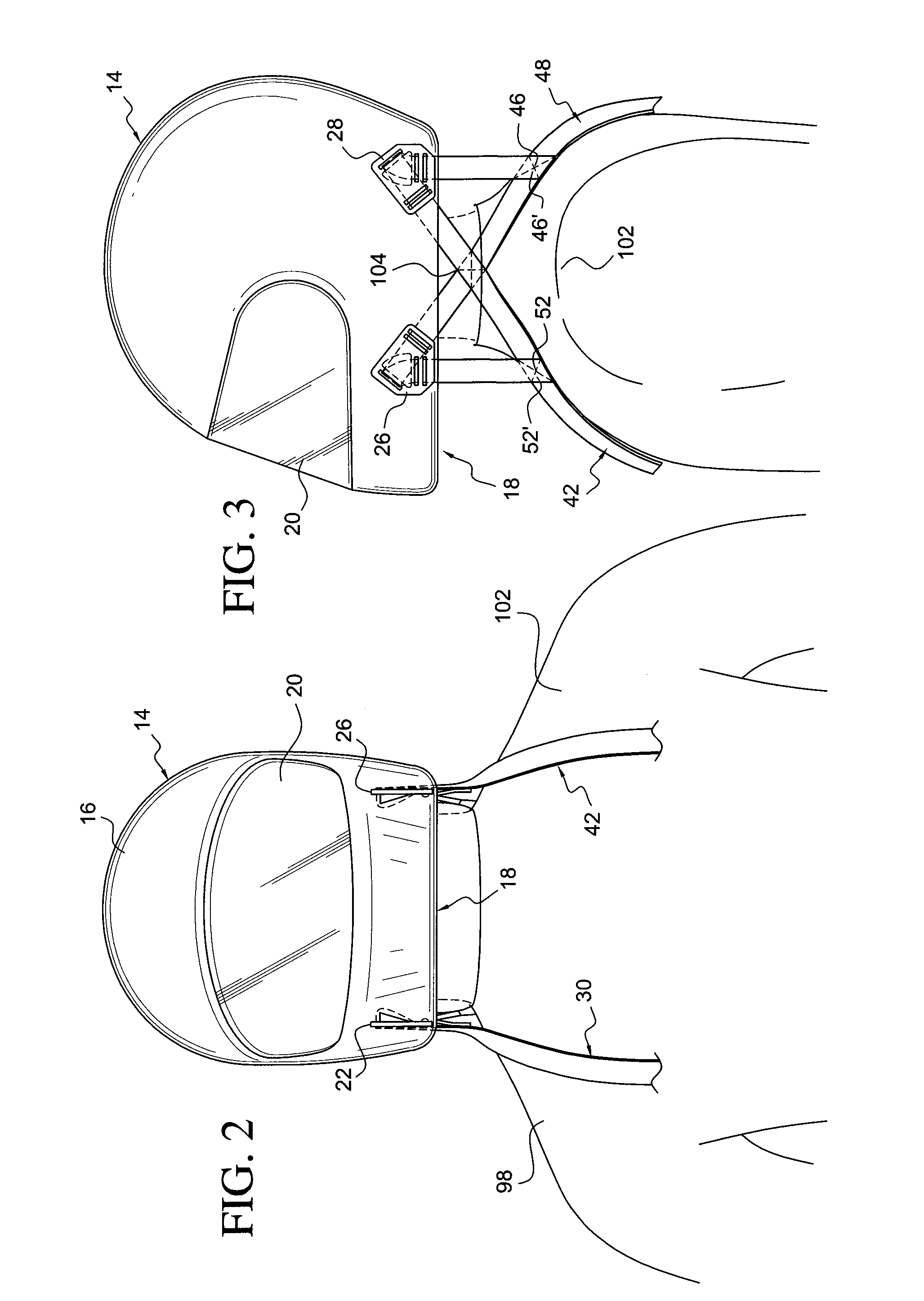
[0048]Referring now to the drawings, wherein the showings are for the purpose of illustrating the preferred embodiments of the invention only and not for the purpose of limiting the same, referring to FIGS. 1-3, a prior art neck restraint system in accordance with my earlier patents is generally shown at 10 being used by a user 12 and attached to a crash helmet 14. The helmet 14 includes a head shell 16 and a bottom opening 18 for providing access for the user's head, and a frontal opening 20 to provide visibility for the user when the user has the helmet on.

[0049]In the first representative embodiment of my earlier invention, the neck restraint system 10 comprises a plurality of laterally symmetrical straps that are attached to the helmet 14 at one end and are removably attached to the user's outfit at opposing second end.

[0050]The neck restraint system 10 comprises a plurality of directive anchors and, more specifically and preferably, four directive anchors wherein a first direct...


PUM


Abstract

A restraint system for limiting the range of motion of an individual's head and flexure of their neck includes an arrangement of straps extending from a head engulfing helmet to a two piece arch-shaped shoulder mounted support member. The arch-shaped shoulder mounted support member includes a front portion, a rear portion and a mechanism for adjusting the curvature of the arch to accommodate individuals of different sizes and also to accommodate different seating positions. A pair of upwardly extending restraint members extends upwardly from the rear portion of the shoulder mounted support member. An upper portion of the upwardly extending restraint member extends upwardly behind the helmet and is tethered to the helmet so that the upwardly extending restraint member limits forward and rear movement of the head.

Description

FIELD OF THE INVENTION[0001]This invention relates a head and neck restraint system for protecting the neck of an individual during a crash of a motor vehicle and more particularly to an improved head and neck restraint system for restricting the forward / aft movement of a motorcycle rider's head in the event of an accident.BACKGROUND FOR THE INVENTION[0002]The use of crash helmets to protect the head of drivers of high speed race cars and motorcycles is well known. In fact the use of crash helmets is commonly accepted for riders of motorcycles. However, the use of a helmet does not limit the range of motion of the driver's neck and does not adequately protect the neck in the event of an accident particularly one of high speed.[0003]For motorcycle racers there is one generally accepted approach for protecting the head and neck of competitors. For example, it is presently believed that a Hans device as disclosed in U.S. Pat. Nos. 6,810,535 and 6,813,782 are commonly used in racing mot...

Claims


Application Information

Patent Timeline
IPC IPC(8): A42B3/04A41D13/00
CPCA41D13/0512A42B3/0473A41D2600/102
Inventor MOTHAFFAR, HUSSAIN
Owner MOTHAFFAR HUSSAIN
Learn More