Caster

a technology of casters and casters, applied in the field of casters, can solve the problems of inconvenient assembly, deterioration of the overall aesthetics of the caster, and easy damage to exposed rivets, so as to prevent the grappling with the other peripheral subjects, the effect of convenient and convenient assembly

Inactive Publication Date: 2010-09-16
CHENG PAO HSIEN
View PDF4 Cites 8 Cited by
  • Summary
  • Abstract
  • Description
  • Claims
  • Application Information

AI Technical Summary

Benefits of technology

[0010]According to the caster of the present invention, a receiving groove is provided in the caster base and a pair of opposite holes for pivoting is provided at both sides of the receiving groove. Then, the pivot shaft of wheel body is fitted into the holes of the receiving groove such that the wheel body can be pivotally mounted in the caster base. In this manner, the assembling of the parts can be conducted without using any tool so as to make the assembly become easier and more convenient. Moreover, the caster is more aesthetic in appearance, as the pivot shaft is provided invisibly in the holes for pivoting of the receiving groove in the caster base. In application, as the pivot shaft is not exposed to the outside of the caster base, grappling with the other peripheral subject can be prevented.

Problems solved by technology

The above caster can reach predetermined easy-moving effect for some items, however it has following defects found in practical application.
Thus, it will cause inconvenience in assembling.
The total aesthetic feature of the caster is deteriorated by the exposure and the protruding of the rivet.
As the caster is assembled by using rivet to hold the caster base and the wheel body in place, the rivet after riveting is protruded outside at both sides of the caster base so that the other peripheral subject is easily grappled with the exposed rivet and might be damaged very easily.

Method used


Image

  • Caster
  • Caster
  • Caster

Examples


Embodiment Construction

[0018]The objects, the technical contents and the expected effectiveness of the present invention will become more apparent from the detailed description of the preferred embodiment in conjunction with the accompanying drawings.

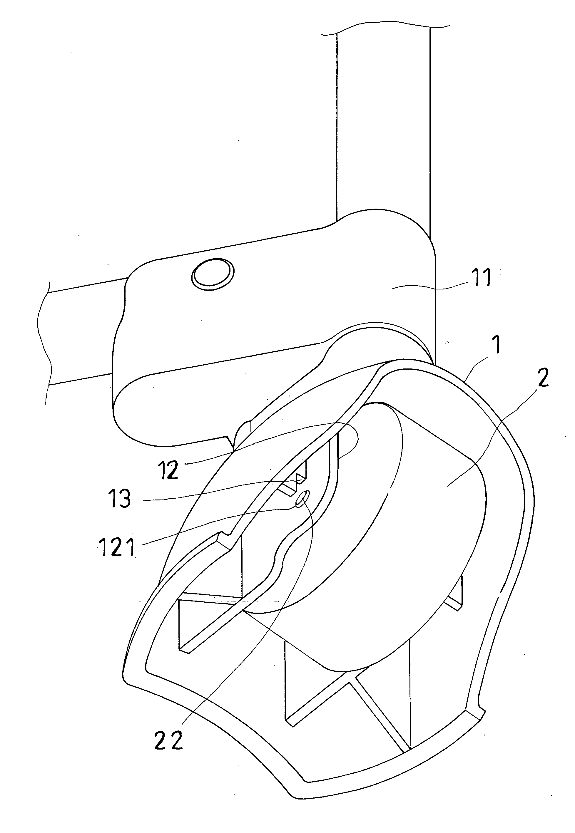
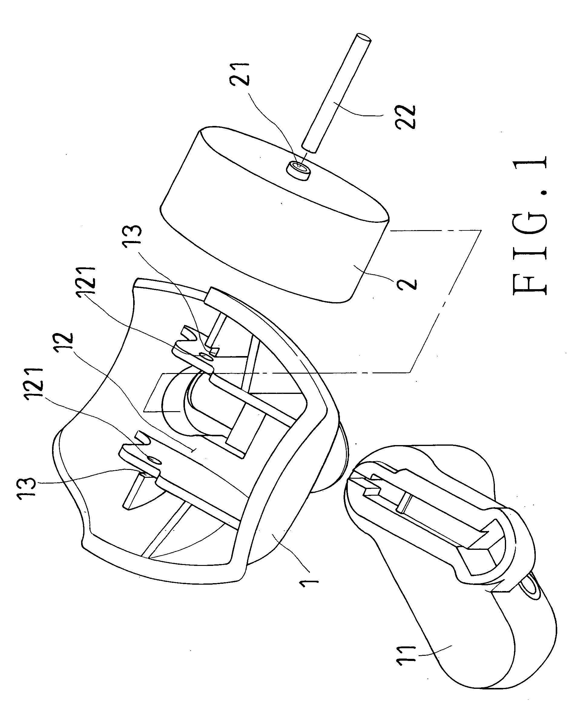
[0019]Firstly referring to FIG. 1 showing a perspective exploded view of the present invention, the caster is composed of a caster base (1) and a wheel body (2). A leg seat (11) is provided on the top end of the caster base (1), and a receiving groove (12) is provided in the caster base (1). A pair of opposite holes (121) for pivoting is provided at both sides of the receiving groove (12), and a pair of stop recesses (13) is provided at the outside of the holes (121) for pivoting. The wheel body (2) has a bore (21) passed through its center in which the pivot shaft (22) is inserted.

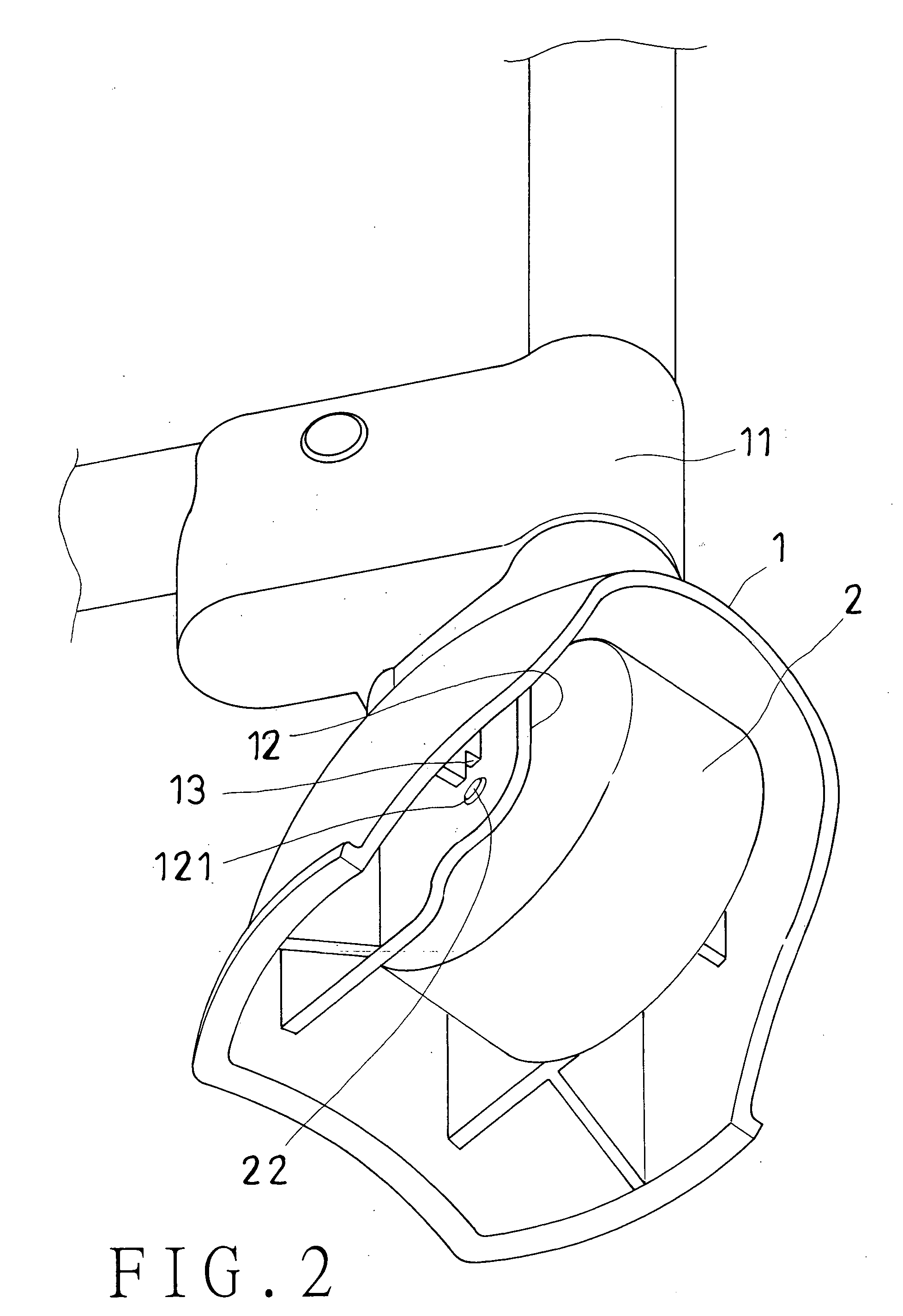
[0020]Referring to FIG. 2 showing the perspective assembly view and FIG. 3 showing a sectional end view of the present invention, the pivot shaft (22) is inserted into the bore (21...


PUM


Abstract

This invention relates to a caster in which a receiving groove is provided internally in the caster base and a pair of opposite holes for pivoting are provided at both sides of the receiving groove. Then, the pivot shaft of the wheel body is fitted into the holes of the receiving groove such that the wheel body can be pivotally fixed in the caster base. In this manner, the assembly of the parts can be conducted easily and conveniently without using any tool. Moreover, the caster has better aesthetic feature in appearance, since the pivot shaft is fitted invisibly in the holes of the receiving groove in the caster base. In application, as the pivot shaft is not exposed to the outside of the caster base, grappling with the other peripheral subject can be prevented.

Description

BACKGROUND OF THE INVENTION[0001]1. Field of the invention[0002]The present invention relates to a caster, particularly to a caster in which the assembling of its parts becomes easier and more convenient, the aesthetic feature is better, and the grappling with the other peripheral subject can be prevented.[0003]2. Brief Description of the Prior Art[0004]Usually, casters are installed on the bottom of infant playyards, stroller or some sorts of furniture for easier moving. The caster (3) shown in FIG. 6 has a caster base (32) pivotally fixed on the bottom of a leg seat (31), a wheel body (33) being inserted within the caster base (32) and a rivet (34) penetrating through the caster base (32) and the wheel body (33) being riveted to hold the same together so that the wheel body (33) can pivot within the caster base (32). In this manner, infant playyards, stroller or furniture mounted with casters can be moved easily.[0005]The above caster can reach predetermined easy-moving effect for...

Claims


Application Information

Patent Timeline
Patent Type & Authority Applications(United States)
IPC IPC(8): B60B33/04
CPCB60B33/0005B60B33/0023B60B33/0026Y10T16/184B60B33/0039B60B33/0049B60B33/0028
Inventor CHENG, PAO-HSIEN
Owner CHENG PAO HSIEN
Why Eureka
Try Eureka