Projection type display device and light source device

a technology of projection type and light source, which is applied in the direction of instruments, lighting and heating apparatus, semiconductor lasers, etc., can solve the problems of invariably increasing focal length, limiting the output obtained by one semiconductor laser, and increasing the aperture diameter of the focusing lens

Active Publication Date: 2010-09-16
PANASONIC CORP
View PDF3 Cites 47 Cited by
  • Summary
  • Abstract
  • Description
  • Claims
  • Application Information

AI Technical Summary

Problems solved by technology

However, there is a limit in the output obtained by one semiconductor laser.
If an attempt is made to increase the number of the solid-state light emitting elements while

Method used


Image

  • Projection type display device and light source device
  • Projection type display device and light source device
  • Projection type display device and light source device

Examples


first embodiment

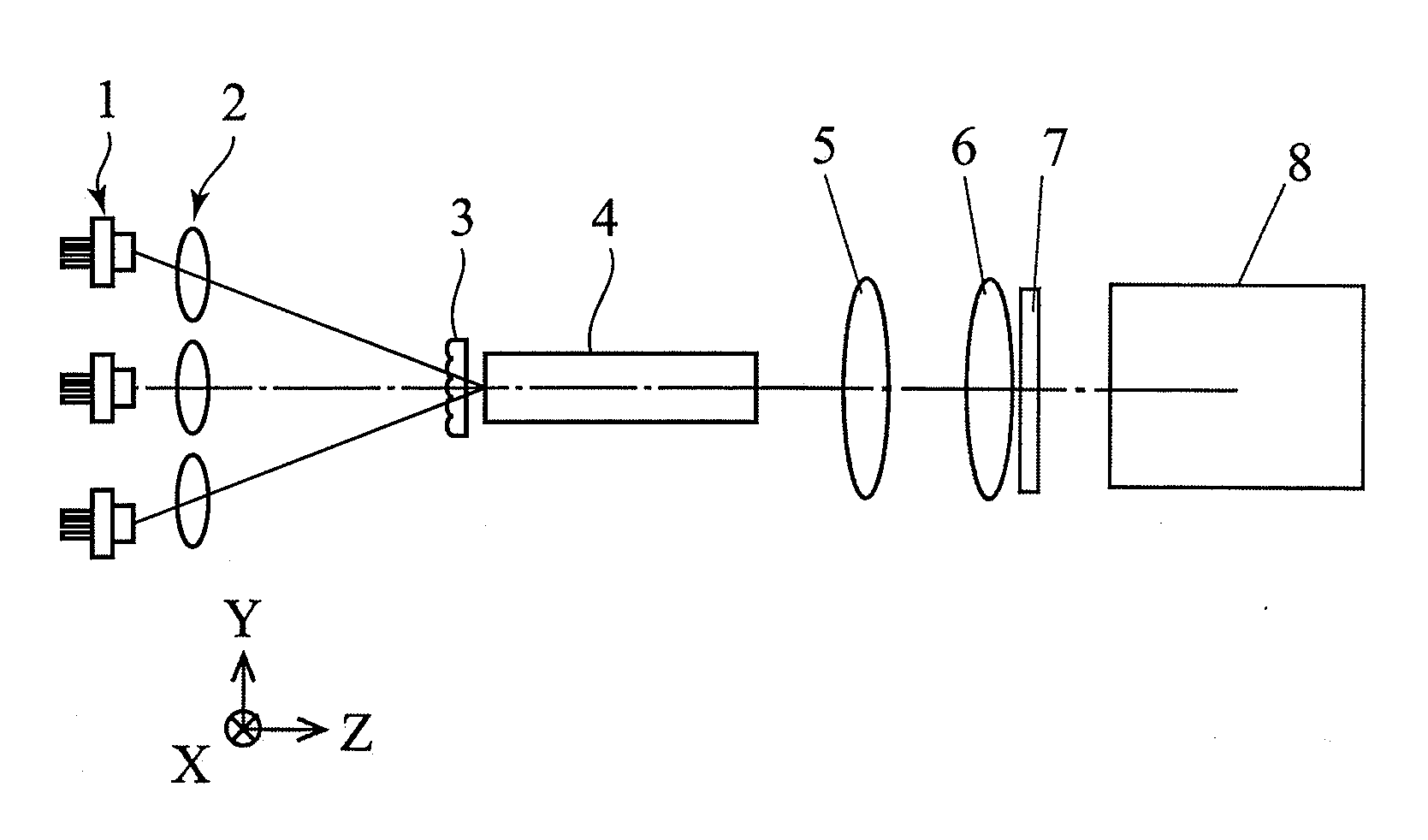
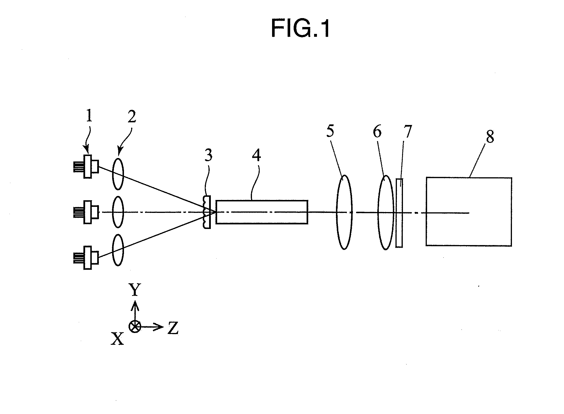
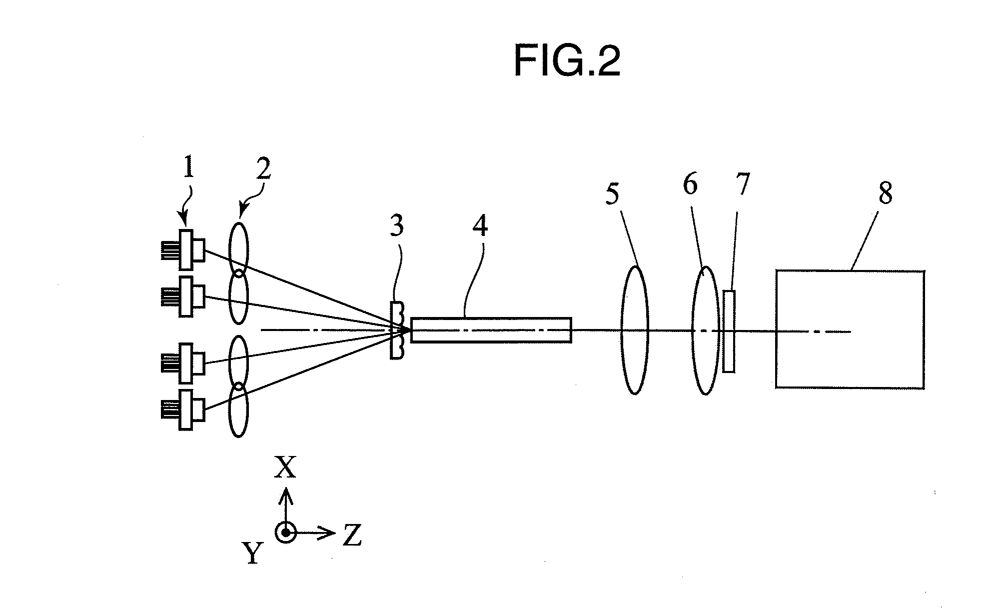
[0036]FIGS. 1 and 2 are views showing a projection type display device according to a first embodiment of the present invention. X-, Y- and Z-axes are defined as shown in FIGS. 1 and 2. FIG. 1 is a YZ side view of the projection type display device according to the first embodiment of the present invention, and FIG. 2 is an XZ side view of the projection type display device according to the first embodiment of the present invention.

[0037]In FIGS. 1 and 2, the projection type display device according to the first embodiment is provided with a laser light source unit 1, a focusing lens unit 2, a lenticular lens 3, a rod integrator 4, a relay lens 5, a field lens 6, a spatial light modulation element 7 and a projection lens 8.

[0038]The laser light source unit 1 is comprised of six semiconductor lasers as described later and emits red or blue laser lights. The focusing lens unit 2 is comprised of six lenses as described later and focuses the laser lights emitted from the laser light sou...

second embodiment

[0057]FIG. 6 is a diagram showing the construction of a projection type display device according to a second embodiment of the present invention. In FIG. 6, the same constituent elements as those in FIGS. 1 and 2 are not described by being identified by the same reference numerals.

[0058]In FIG. 6, the projection type display device according to the second embodiment is provided with a laser light source unit 1, a focusing lens unit 2, a lenticular lens 3, a rod integrator 4, a relay lens 5, a field lens 6, a spatial light modulation element 7, a projection lens 8, a convex lens 9 and a concave lens 10. The convex lens 9 and the concave lens 10 constitute a telephoto type optical system, and a parallel light incident on the convex lens 9 is focused to an incident surface of the rod integrator 4. The operation of the projection type display device according to the second embodiment of the present invention is described below with reference to FIG. 6.

[0059]The light emission regions of...

third embodiment

[0061]FIG. 7 is a diagram showing the construction of a projection type display device according to a third embodiment of the present invention. In FIG. 7, the same constituent elements as those in FIGS. 1 and 2 are not described by being identified by the same reference numerals.

[0062]In FIG. 7, the projection type display device according to the third embodiment is provided with a laser light source unit 1, a focusing lens unit 2, a lenticular lens 3, a rod integrator 4, a relay lens 5, a field lens 6, a spatial light modulation element 7, a projection lens 8, a first convex lens 11 and a second convex lens 12. An interval between the first and second convex lenses is set at about the sum of focal lengths of the respective lenses, and lights focused by the first convex lens 11 are focused to an incident end surface of the rod integrator 4 by the second convex lens 12. The first and second convex lenses 11, 12 constitute a telephoto type optical system, and a lens interval can be m...


PUM


Abstract

Miniaturization is realized and high-output lights are obtained by optimizing the arrangement of a laser light source unit and a homogenizer.
A laser light source unit 1 has a light emission region for emitting an elliptical laser light. A focusing lens unit 2 focuses the laser light emitted from the laser light source unit 1. A rod integrator 4 has a rectangular incident surface on luminous flux focused by the focusing lens unit 2. A spatial light modulation element 7 modulates the laser light emitted from the rod integrator 4. A projection lens 8 projects the laser light modulated by the spatial light modulation element 7. The incident surface of the rod integrator 4 has a rectangular shape, and the laser light source unit 1 is arranged such that a longer axis direction of the light emission region and a longer side direction of the incident surface of the rod integrator are parallel.

Description

TECHNICAL FIELD[0001]The present invention relates to a projection type display device and a light source device using a laser light source.BACKGROUND ART[0002]Front projection type display devices and rear projection type display devices using a spatial light modulation element such as a transmissive / reflective liquid crystal element or a micromirror array are known as large-screen display devices. The front projection type display devices and the rear projection type display devices are divided into a type in which three spatial light modulation elements are provided in correspondence with three primary colors of red, green and blue to form a color image and a type in which lights of three primary colors are projected to one spatial light modulation element in a time sharing manner to combine a color image. An ultra high pressure mercury lamp has been conventionally used as a light source of a projection type display device. However, with the recent years' commercialization of hig...

Claims


Application Information

Patent Timeline
IPC IPC(8): G03B21/14G02B27/48F21V13/02G02B27/09G02B27/18G03B21/00H01S3/00H01S5/022
CPCG02B27/0994G03B21/14G03B21/2033H01S3/005H01S3/2383G02B19/0028H04N9/3129H04N9/3161G02B19/0057G02B19/009H01S5/4012G03B21/2013G03B21/2053
Inventor ITOH, TATSUOMIZUSHIMA, TETSUROKASAZUMI, KENICHIYAMAMOTO, KAZUHISA
Owner PANASONIC CORP
Why Eureka
Try Eureka