Flexible display device

a display device and flexible technology, applied in static indicating devices, non-linear optics, instruments, etc., can solve the problems of reducing the stress concentration only slightly, the level of delamination of the sealing member is only somewhat reduced, and the adverse effect of highly adhesive sealing materials on the liquid crystal layer is greater, so as to achieve efficient delamination of the sealing member, reduce the thickness of the display device, and reduce the weight

Inactive Publication Date: 2010-09-23
SHARP KK
View PDF6 Cites 29 Cited by
  • Summary
  • Abstract
  • Description
  • Claims
  • Application Information

AI Technical Summary

Benefits of technology

[0025]At this time, since the curved portion of the sealing member according to a preferred embodiment of the present invention has no corners like those in conventional examples, a delamination stress is not concentrated on the corners. Thus, convex portions are less likely to be formed in the second substrate near the sealing member. Even if convex portions are formed, such convex portions can be concentrated in a small region near the top of the curved portion of the sealing member (the middle position in the longitudinal direction of the curved portion).
[0026]Thus, even if the inner side of the sealing member is reinforced, it is enough to reinforce only a region near the top of the curved portion. This enables delamination of the sealing member to be reduced while ensuring flexibility, thin thickne

Problems solved by technology

However, this stress concentration is reduced only slightly, and the level of delamination of the sealing member is only somewhat reduced.
However, highly adhesive sealing materials tend to have a greater adverse effect on the liquid crystal layer (an effect due to elution of adhesive components to liquid crystal).
On the other hand, elastic sealing members have, in principle, poorer moisture permeability.

Method used


Image

  • Flexible display device
  • Flexible display device
  • Flexible display device

Examples


first preferred embodiment

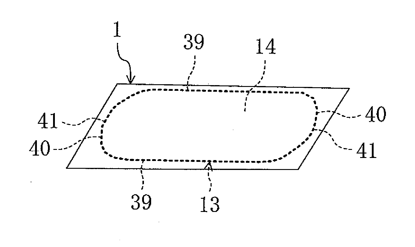
[0040]FIGS. 1-3 show a first preferred embodiment of the present invention. In the first preferred embodiment, an LCD device 1 will be described as an example of display devices.

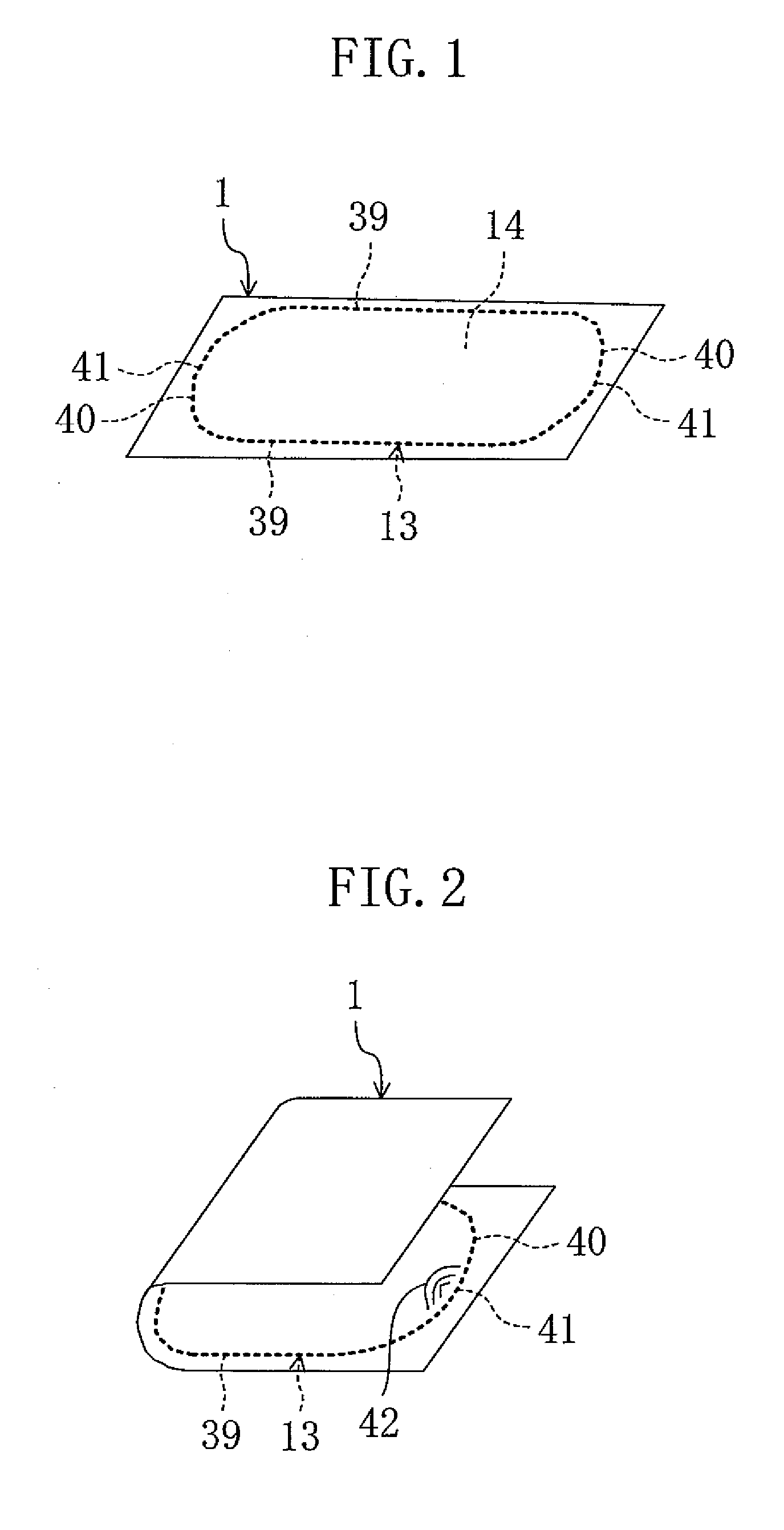
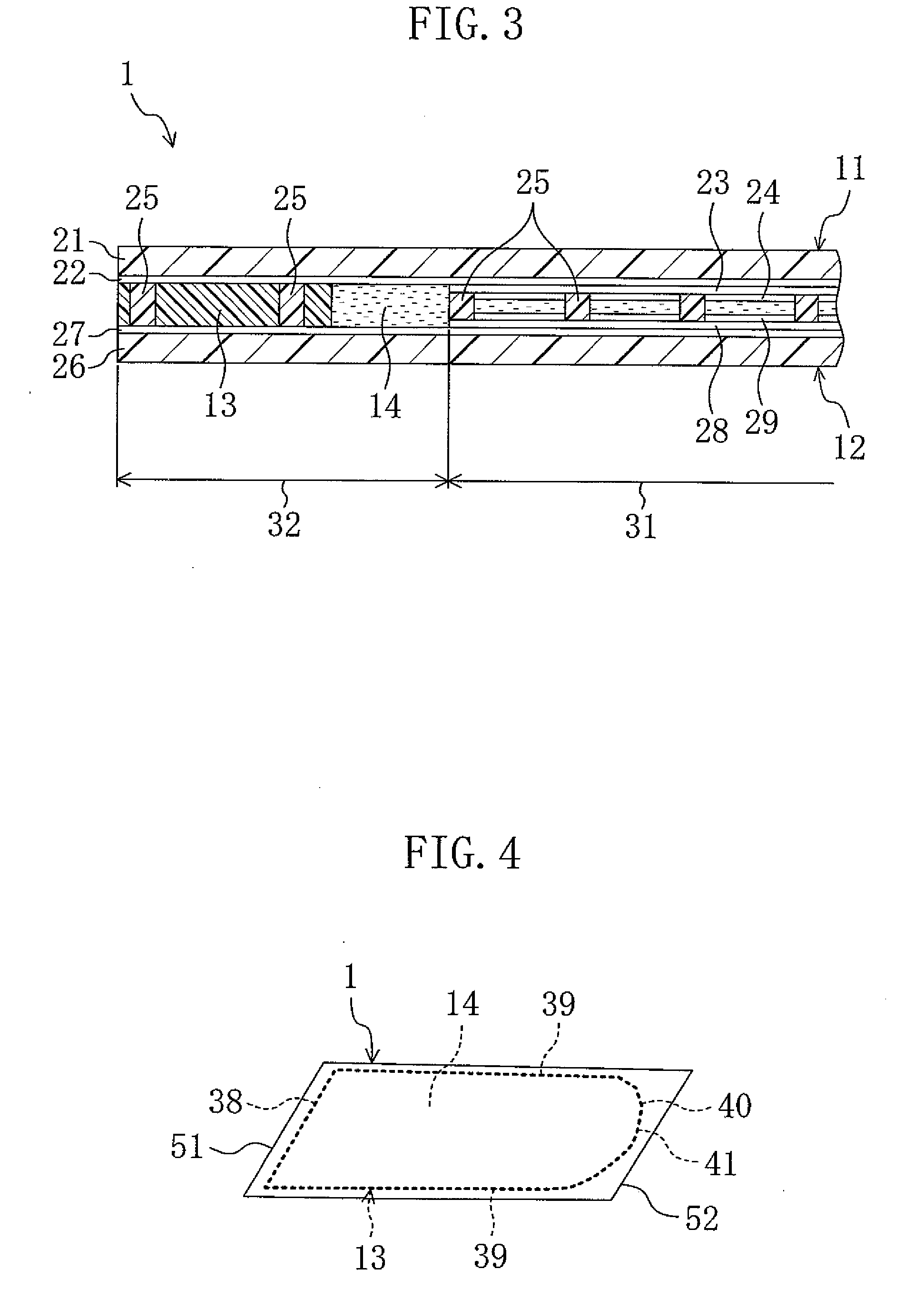
[0041]FIG. 1 is a perspective view schematically showing the external appearance of the LCD device of the first preferred embodiment. FIG. 2 is a perspective view schematically showing an overview of the LCD device of the first preferred embodiment in a bent state. FIG. 3 is an enlarged cross-sectional view showing a main part of the LCD device.

[0042]As shown in FIG. 3, the LCD device 1 includes a flexible first substrate 11, a flexible second substrate 12 arranged so as to face the first substrate 11, a liquid crystal layer 14 as a display medium layer provided between the first substrate 11 and the second substrate 12, and a sealing member 13 arranged to surround the liquid crystal layer 14 between the first substrate 11 and the second substrate 12. The LCD device 1 is configured so that the entire LCD dev...

second preferred embodiment

[0059]FIG. 4 shows a second preferred embodiment of the present invention.

[0060]FIG. 4 is a perspective view schematically showing the external appearance of an LCD device of the second preferred embodiment. Note that, in the following preferred embodiments, the same elements as those in FIGS. 1-3 are denoted by the same reference characters, and detailed description thereof will be omitted.

[0061]Although the sealing member 13 preferably includes the pair of linear portions 39 and the pair of curved portions 40 in the first preferred embodiment, only one curved portion 40 is preferably provided in the sealing member 13 in the second preferred embodiment.

[0062]That is, the LCD device 1 includes a fixed end 51 that is supported by, and fixed to an external element, and a bent end 52 positioned so as to face the fixed end 51 and subjected to an external force.

[0063]The sealing member 13 preferably includes two first linear portions 39 extending parallel or substantially parallel to eac...


PUM


Abstract

A display device includes a display medium layer positioned between a flexible first substrate and a flexible second substrate, and a sealing member arranged to surround the display medium layer between the first substrate and the second substrate. The sealing member includes a curved portion that is curved so as to protrude outward toward a side opposite to the display medium layer as viewed from a direction normal to a surface of the first substrate in a flat state.

Description

BACKGROUND OF THE INVENTION[0001]1. Field of the Invention[0002]The present invention relates to flexible display devices.[0003]2. Description of the Related Art[0004]In recent years, so-called flat panel displays have been widely used as display devices in various fields. Examples of the flat panel displays include liquid crystal display (LCD) devices, and organic electroluminescence (EL) display devices. The LCD devices and the organic EL display devices have been used in the fields of mobile displays, such as mobile phones and personal digital assistants (PDA), due to their features such as thin thickness and light weight. Further reduction in thickness and weight, and flexibility of display devices have been desired in these fields, and studies have been conducted to replace glass substrates with flexible substrates such as plastic.[0005]Problems of display devices using flexible substrates will be described below with respect to an LCD device as an example. As shown in a cross-...

Claims


Application Information

Patent Timeline
IPC IPC(8): G09G3/36
CPCG02F1/1339G02F1/133305
Inventor WATANABE, NORIKO
Owner SHARP KK
Why Eureka
Try Eureka