
Boom extension apparatus

Inactive Publication Date: 2010-09-23
TESINSKY VINCENT E
View PDF7 Cites 7 Cited by
  • Summary
  • Abstract
  • Description
  • Claims
  • Application Information

AI Technical Summary

Benefits of technology

[0007]A boom extension apparatus is provided for effectively extending the boom arms on a prime mover such as a skid-steer loader or vehicle so that the implement on the extension apparatus may be lifted to a higher location or moved father away from the vehicle. The extension apparatus of this invention includes an extender frame having rearward and forward ends with the rearward end of the extender frame having a female quick-attach mounting structure mounted thereon adapted to be quickly attached to the conventional male implement quick-attach structure pivotally mounted on the forward ends of the boom arms.
[0008]The forward end of the extender frame has a male implement quick-attach mounting structure thereon which is pivotally secured thereto and which is adapted to have an implement such as a bucket, bale spear, grapple, etc. quickly and easily secured thereto by way of the female quick-attach structure at the rear end of the implement.
[0013]Yet another object of the invention is to provide a boom extension apparatus which is quickly and easily attachable to the conventional quick-attach structure on the boom arms of a skid-steer loader or the like.

Problems solved by technology

Moreover, this Summary is not intended for use as an aid in determining the scope of the claimed subject matter.

Method used


Image

  • Boom extension apparatus
  • Boom extension apparatus
  • Boom extension apparatus

Examples


Embodiment Construction

[0022]Embodiments are described more fully below with reference to the accompanying figures, which form a part hereof and show, by way of illustration, specific exemplary embodiments. These embodiments are disclosed in sufficient detail to enable those skilled in the art to practice the invention. However, embodiments may be implemented in many different forms and should not be construed as being limited to the embodiments set forth herein. The following detailed description is, therefore, not to be taken in a limiting sense in that the scope of the present invention is defined only by the appended claims.

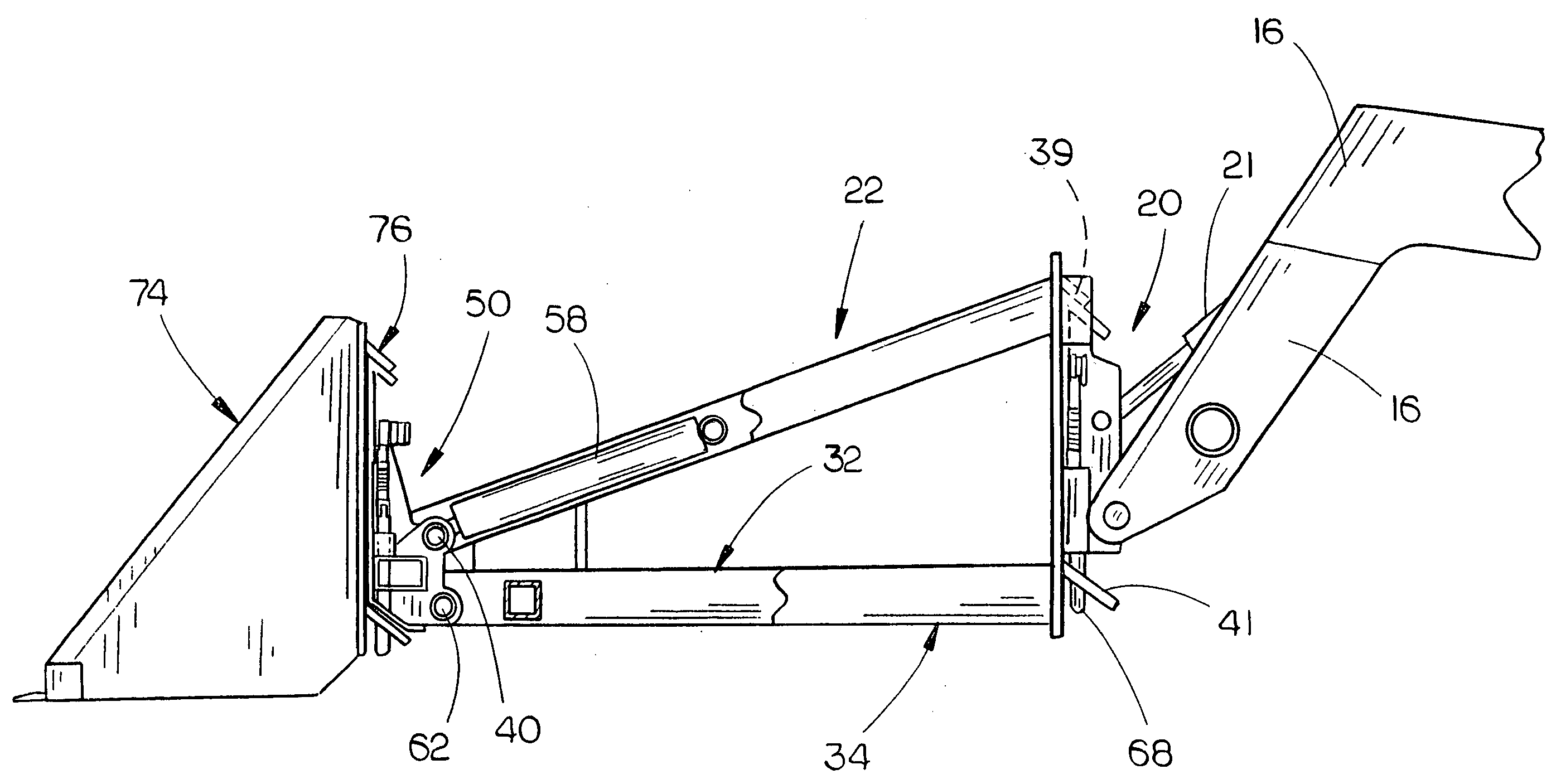
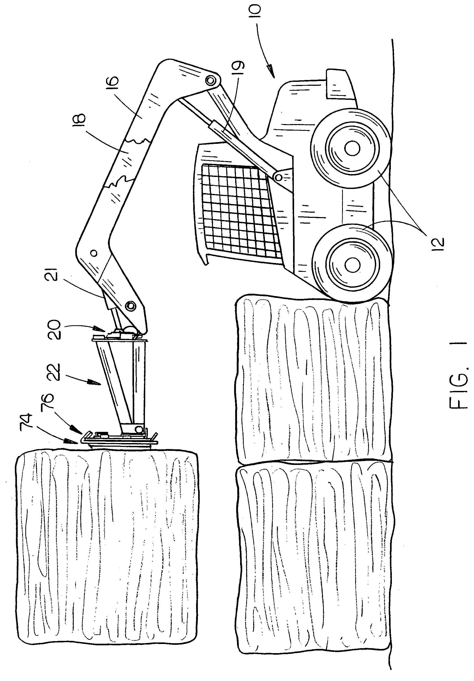
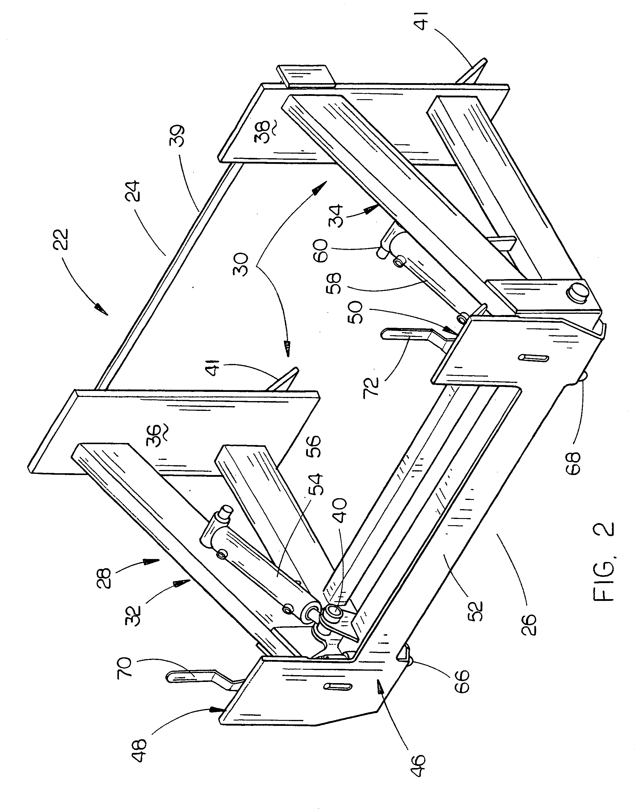
[0023]The numeral 10 refers to a prime mover such as a conventional skid-steer loader or vehicle having a pair of driven wheels 12 at one side thereof and a pair of driven wheels at the other side thereof which are identical to driven wheels 12. Loader 10 includes a pair of boom arms 16 and 18 which are pivoted at their rearward ends to the loader and which extend forwardly therefr...


PUM


Abstract

A boom extension apparatus is provided for a prime mover such as a skid-steer loader or vehicle wherein the rearward end of the boom extension apparatus is quickly and easily attachable to the forward ends of the boom arms of the skid-steer loader. The forward end of the boom extension apparatus is quickly and easily attachable to the rearward end of an implement such as a bucket, bale spear, etc.

Description

BACKGROUND OF THE INVENTION[0001]1. Field of the Invention[0002]This invention relates to a boom extension apparatus for a prime mover such as a skid-steer loader or vehicle.[0003]2. Description of the Related Art[0004]Skid-steer vehicles which are commonly referred to as skid-steer loaders such as the popular Bobcat® skid-steer loader include a wheeled frame having a pair of drive wheels at one side thereof and a pair of drive wheels at the other side thereof. A pair of elongated boom arms are pivotally connected to the wheeled frame at their rearward ends and extend forwardly therefrom. The boom arms are usually raised and lowered by means of a pair of hydraulic cylinders extending between the frame and the boom arms. Inasmuch as the skid-steer loaders normally are smaller than conventional farm tractors, the boom arms of the skid-steer loaders have a limited height and reach. In most cases, the forward ends of the boom arms have a conventional implement quick-attach apparatus, as...

Claims


Application Information

Patent Timeline
IPC IPC(8): B66F9/075
CPCB66F9/16B66F9/12
Inventor TESINSKY, VINCENT E.
Owner TESINSKY VINCENT E
Features
  • Generate Ideas
  • Intellectual Property
  • Life Sciences
  • Materials
  • Tech Scout
  • Unparalleled Data Quality
  • Higher Quality Content
  • 60% Fewer Hallucinations
Learn More