Camara sight with smart phone mount

Active Publication Date: 2018-08-30
CAMPBELL ROBERT MARSHALL
View PDF0 Cites 10 Cited by
  • Summary
  • Abstract
  • Description
  • Claims
  • Application Information

AI Technical Summary

Benefits of technology

[0030]It is yet another objective of the present invention to provide an improved firearm accessory that is a smart phone mount and sight systems for firearms that improve viewing of targets through the primary firearm sights on the firearm or of the target image provided by the device's own sight adjustable sight that provides advanced targeting abilities with a wide field of view of the target image and surrounding area, with the target reticle always remaining perfectly-centered in the smart device's screen to the smart phone or smart device that is mounted on this accessory that is cost effective and operationally efficient.
[0031]It is yet another objective of the present invention to provide a more efficient improved and superior accessory or smart phone mount and sight systems for firearms that provide the user with a wide view of the surrounding area acquired by means of the camera lens in this invention, mounted far enough forward in the sight housing and close enough to the forward viewing window behind the reflected reticle to acquire a full wide unobstructed view of the target image and surrounding area with the sight's target reticle always remaining perfectly centered in the smart device's screen.
[0032]It is yet another objective of the present invention to provide a soldier with a view of his entire surr

Problems solved by technology

All have other advantages and disadvantages to each other, consisting of things like cost, size, power consumption, and abilities, with one of these more cost inhibitive options possessi

Method used


Image

  • Camara sight with smart phone mount
  • Camara sight with smart phone mount
  • Camara sight with smart phone mount

Examples


Example

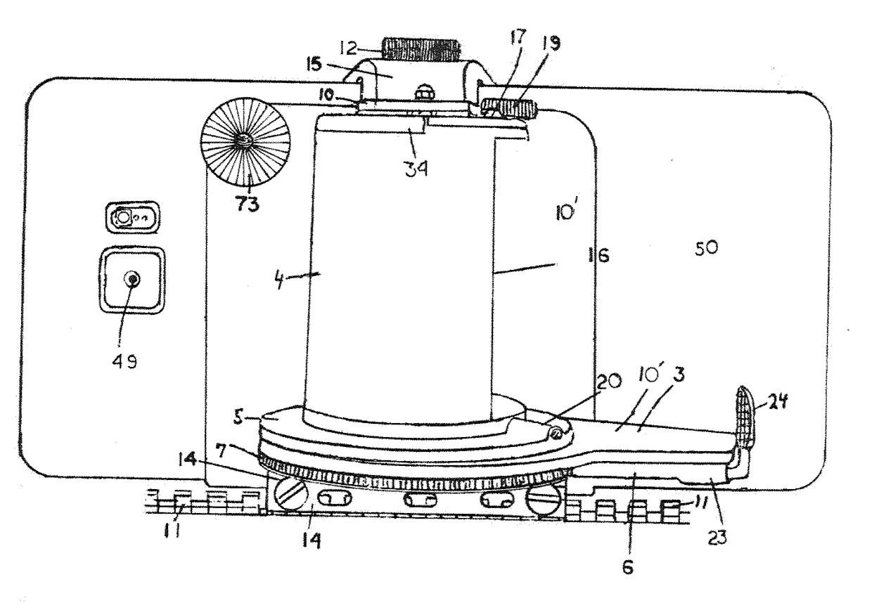
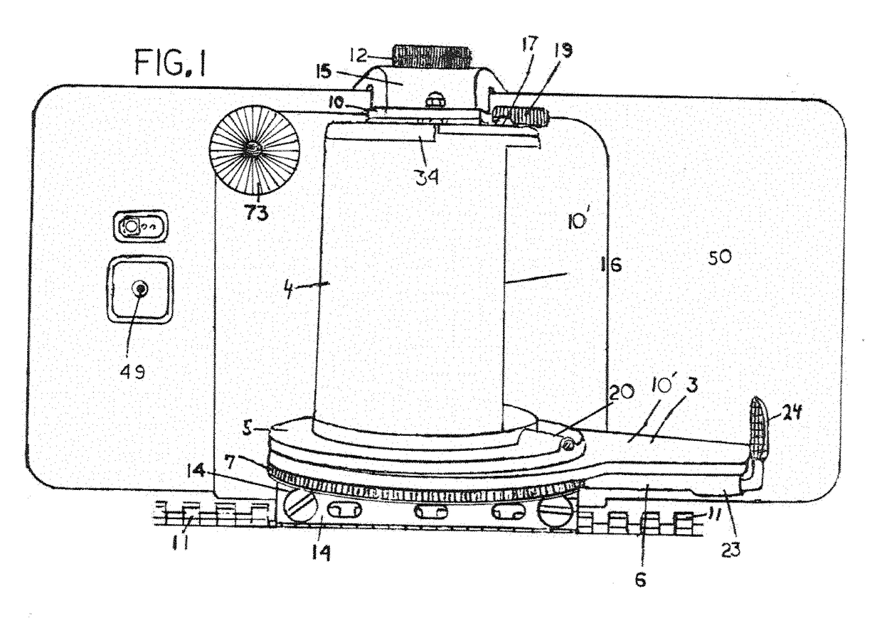
[0074]FIG. 1 is a drawing of the invention in its first embodiment being an HD infrared viewing camera with its own Wi-Fi transmitting module. This camera vertically adjusts to various heights to acquire the best vantage point to receive the target image received from other various sights on the firearm such as red dot sights and scopes, and transmits its image to the smart phone that mounts on the device. The height adjustable camera housing, #4, is integral to the rail mount, #14, so the camera always remains parallel to the weapon's rail. Then smart phone mount rotates and locks into various positions from side to side of the firearm in a radius up to approximately 270 degrees. This is accomplished by pulling the finger pull, #24, which is integral to a spring loaded pin or rod that is housed in rod housing, #6, with the spring that maintains tension to the rod housed in housing, #23. This pin, in turn, locks into teeth or notches, #7, which are an integral part of the rail mount...

Example

[0088]FIG. 12 A through FIG. 17 are drawings of this invention in its second embodiment which is a non-height adjustable, but sight adjustable, HD infrared viewing camera with its own Wi-Fi transmitting module that transmits its sighted-in target image and reticle image to the smart phone or tablet that mounts to this device. This embodiment of this invention works independently from other sights on the firearm so that the camera sight and smart phone or tablet work together as a complete unit. FIG. 12A shows a profile view of this device in its second embodiment with the infrared illuminator #43, and rear viewing camera #78, and battery compartment and viewing screen housing #77, in accordance with the principles of the present embodiment.

[0089]These drawings, 12 A through FIG. 19, also show this device with an integral infrared illuminator in that all of the cameras used in these camera sights have infrared viewing capabilities so that they work almost as well at night as they do ...


PUM


Abstract

A camera sighting device, configured for securing about a firearm, the sighting device housed in a housing, with a smart phone or smart device mounting platform rotatably coupled thereon, with an additional rear viewing camera, integral or attachable to an armature. This said armature, additionally passes through an open portion of a clamping device, that is attachable to a threaded base portion, of the back side of said smart device mounting platform, and is both height and angularly adjustable. This said sighting device, provides the target image that is either received from other target viewing devices mounted on the firearm, or provides its own target image, to the smart device, where this said target image is viewable by the user, from any position that the user could position himself in relation to the firearm, by means of the said rotatable smartphone or smart device mounting platform. The image of the area behind the user would also be provided at the same time, by means of the said height and angularly adjustable rear viewing camera, that would either display its image simultaneously in a window of, or on, a split screen on the smart device's viewing screen, or would provide the image behind the user simultaneously, in its own viewing screen.

Description

CLAIM OF PRIORITY[0001]This application is being filed as a non-provisional patent application under 35 U.S.C. § 111(b) and 37 C.F.R. § 153(b). This application claims priority under 35 U.S.C. § 119(e) to U.S. Provisional Patent Application Ser. No. 62 / 452,986 filed on Jan. 31, 2017, and U.S. Provisional Patent Application Ser. No. 62 / 467,197 filed on Mar. 5, 2017, the contents of which are incorporated herein by reference.FIELD OF INVENTION[0002]The present invention generally relates to the field of firearm accessories. Firearm accessories consist of a wide range of devices that attach to and enhance the performance of, or simply work in conjunction with a fire arm, all of which are produced to enhance the abilities of the firearm in one way or another. These accessories consist of various types of sights, scopes, night vision, laser sights, range finders, etc. as well as things like regular or infra-red high-powered lights, tripods, various types of mounting rail systems etc. Thi...

Claims


Application Information

Patent Timeline
IPC IPC(8): F41G1/473H04N5/225F41G11/00H04M1/02H04M1/72412
CPCF41G1/473H04N5/2252H04N5/2253F41G11/005H04M1/026H04M1/04H04M2250/52F41G11/003F41J5/10H04M1/72412H04N23/57H04N23/51H04N23/54
Inventor CAMPBELL, ROBERT MARSHALL
Owner CAMPBELL ROBERT MARSHALL
Why Eureka
Try Eureka