
Vehicle window cleaning apparatus and system

a technology for vehicle windows and cleaning tools, applied in the direction of carpet cleaners, metal-working hand tools, brushes, etc., can solve the problems of significant spray deposited on the horizontal surfaces of the underlying surfaces, the edges of cleaning tools are difficult to get close to the extreme lower edges of the windshield and backlight, and the ineffective cleaning of the inner surface of the vehicle window. , to achieve the effect of convenient mounting and removal, easy attachment and detachabl

Inactive Publication Date: 2005-08-16
K & R IND +1
View PDF38 Cites 8 Cited by
  • Summary
  • Abstract
  • Description
  • Claims
  • Application Information

AI Technical Summary

Benefits of technology

[0014]In another aspect of the present invention, the above-described cleaning apparatus forms part of a cleaning system which includes a first handle, a plurality of cleaning elements of the same or different shape, and a plurality of paddles, at least some of which have a different peripheral shape. The cleaning elements are easily mountable on any of the paddles to enable a clean and dry cleaning element to be used whenever needed. In addition, each of the paddles is quickly and easily attachable and detachable from the handle for ease in using the cleaning system of the present invention.
[0016]Generally, the second handle is of one-piece construction with lower S-shaped side legs extending between an upper hand engagement portion and the ends. The S-shape side legs are is configured to absorb forces exerted by the user on the handle during movement of the paddle. The second set receivers may also be formed on the same paddles in the first aspect of the invention. This enables either the first or second handles to be employed with any paddle thereby further enhancing the interchangeability of the various components of the cleaning system of the present invention.
[0020]In yet another aspect, the receiver has a magnetic latch which holds a pivotal flap in the closed position rotatably trapping a rod-like end portion of the handle in the receiver. The flap may be easily moved to the open position to allow the handle to be disengaged.
[0021]The cleaning apparatus from the receiver and cleaning system of the present invention affords numerous advantages over prior cleaning apparatus devised for cleaning various surfaces, such as the interior and exterior surfaces of vehicle windows. The present cleaning system enables a plurality of different shaped paddles and attached washing, scrubbing and drying elements to be detachably mounted on a handle for use in practically any surface cleaning application, such as vehicle windows. The cleaning apparatus lends itself to use as part of a cleaning system formed of one or more handles, a plurality of different shaped paddles, and releasably attachable cleaning elements. The cleaning elements are easily mountable and removable from the paddles and the paddles are easily attachable and detachable to any of the handles. The present cleaning apparatus enables a user, for example, to easily reach the lower edges of the interior surface of vehicle windows adjacent to the vehicle dash board or rear backlight despite the extreme angles of such windows with respect to interior vehicle surfaces and the adjacent rear view mirror, steering wheel or rear center brake light assembly housing.

Problems solved by technology

However, such tools are ineffective in cleaning the inner surface of vehicle windows.
The extreme angles of the vehicle windshield and backlight with respect to the dashboard and rear seat shelf in conjunction with adjacent vehicle components, such as the rear view mirror, steering wheel and rear, center brake light housing make it difficult to get the edges of a cleaning tool close to the extreme lower edges of the windshield and backlight.
In addition, applying fluid, which is typically in the form of a spray, to the inner surfaces of the windshield and backlight results in a significant amount of the spray being deposited on the underlying horizontal surfaces adjacent to the windows, such as the vehicle dashboard and the rear shelf.
While a user may be able with a considerable amount of effort to clean most of the inner surface of the vehicle window, it is still difficult to completely clean the edges of the window and, more importantly, the lower edges of a vehicle windshield and backlight.
However, each of these tools is specifically devised for a single type of cleaning operation, such as scrubbing or drying, but not both.

Method used


Image

  • Vehicle window cleaning apparatus and system
  • Vehicle window cleaning apparatus and system
  • Vehicle window cleaning apparatus and system

Examples


Embodiment Construction

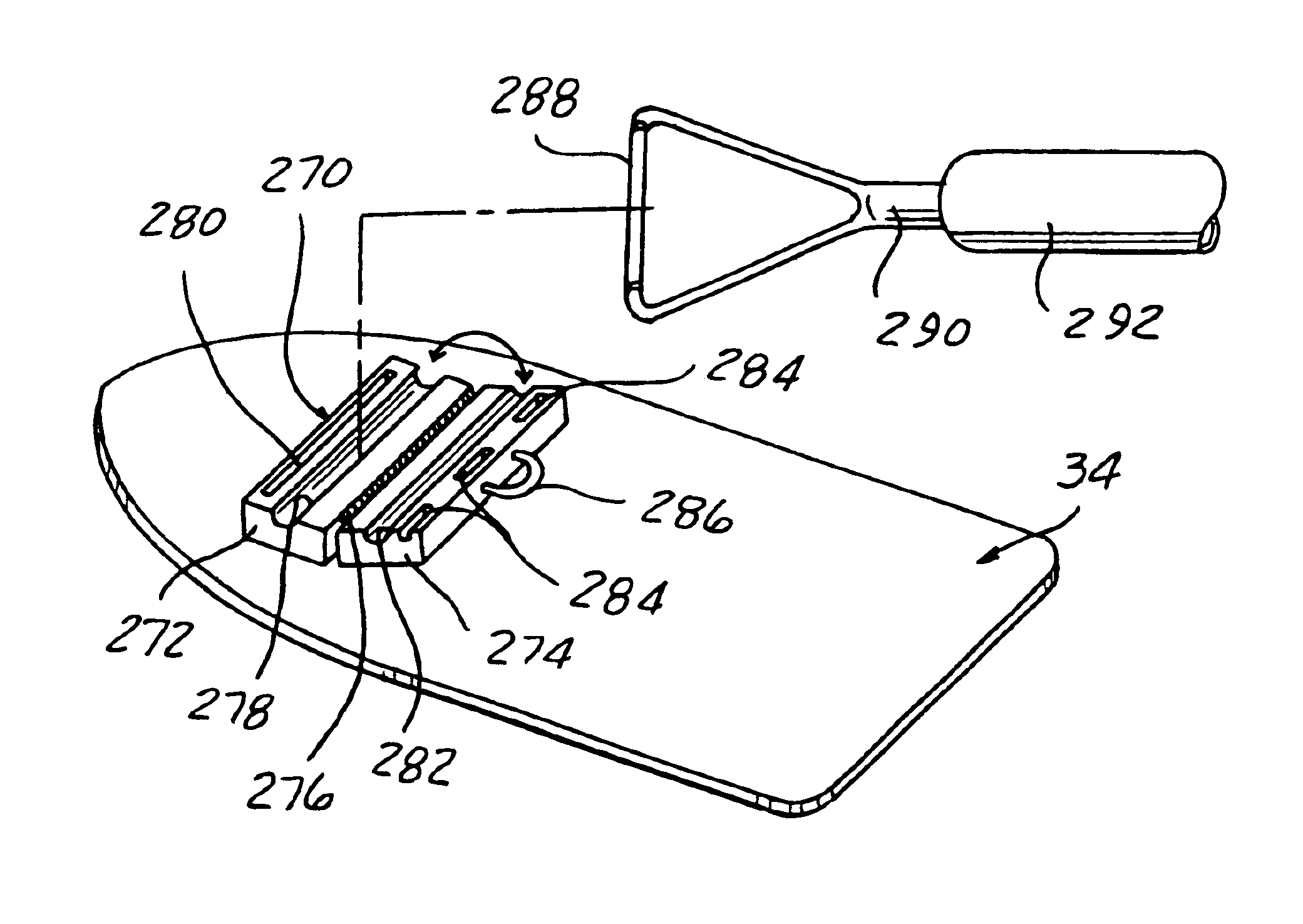
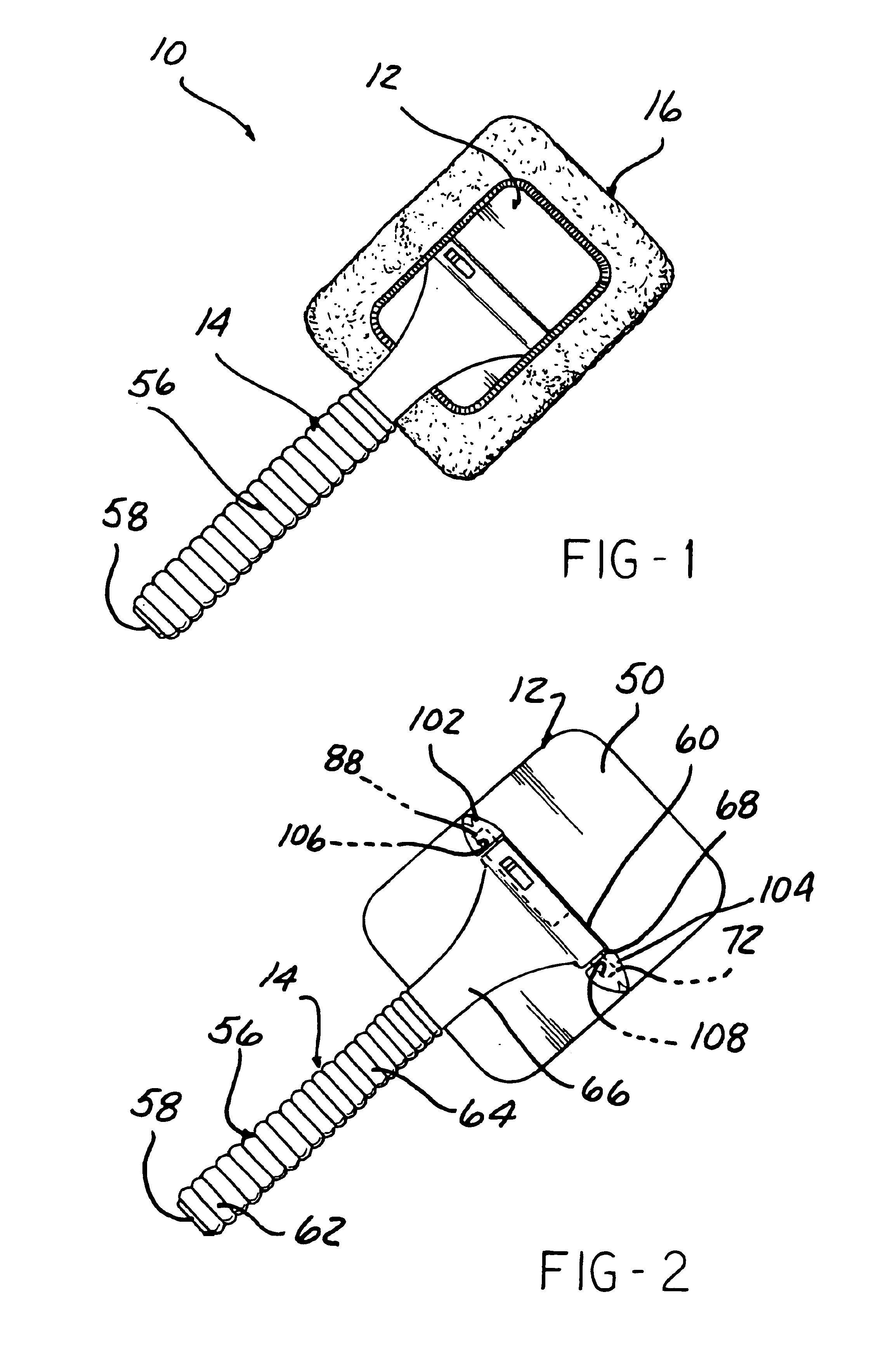
[0041]Referring now to the drawing, and to FIGS. 1-5 in particular, there is depicted a first aspect of a cleaning apparatus 10 constructed in accordance with the teachings of the present invention. It will be understood that although the following description of the use of the cleaning apparatus 10 in cleaning and drying the interior surfaces of vehicle windows, the cleaning apparatus 10 may also be applied in a variety of other cleaning applications, such as to clean and dry the exterior surface of the vehicle windows, house or building windows, mirrors, or practically any surface that requires the use of a cleaning fluid and its removable from the surface being cleaned.

[0042]In general, the cleaning apparatus 10, includes a paddle 12, a handle 14, and a drying element 16.

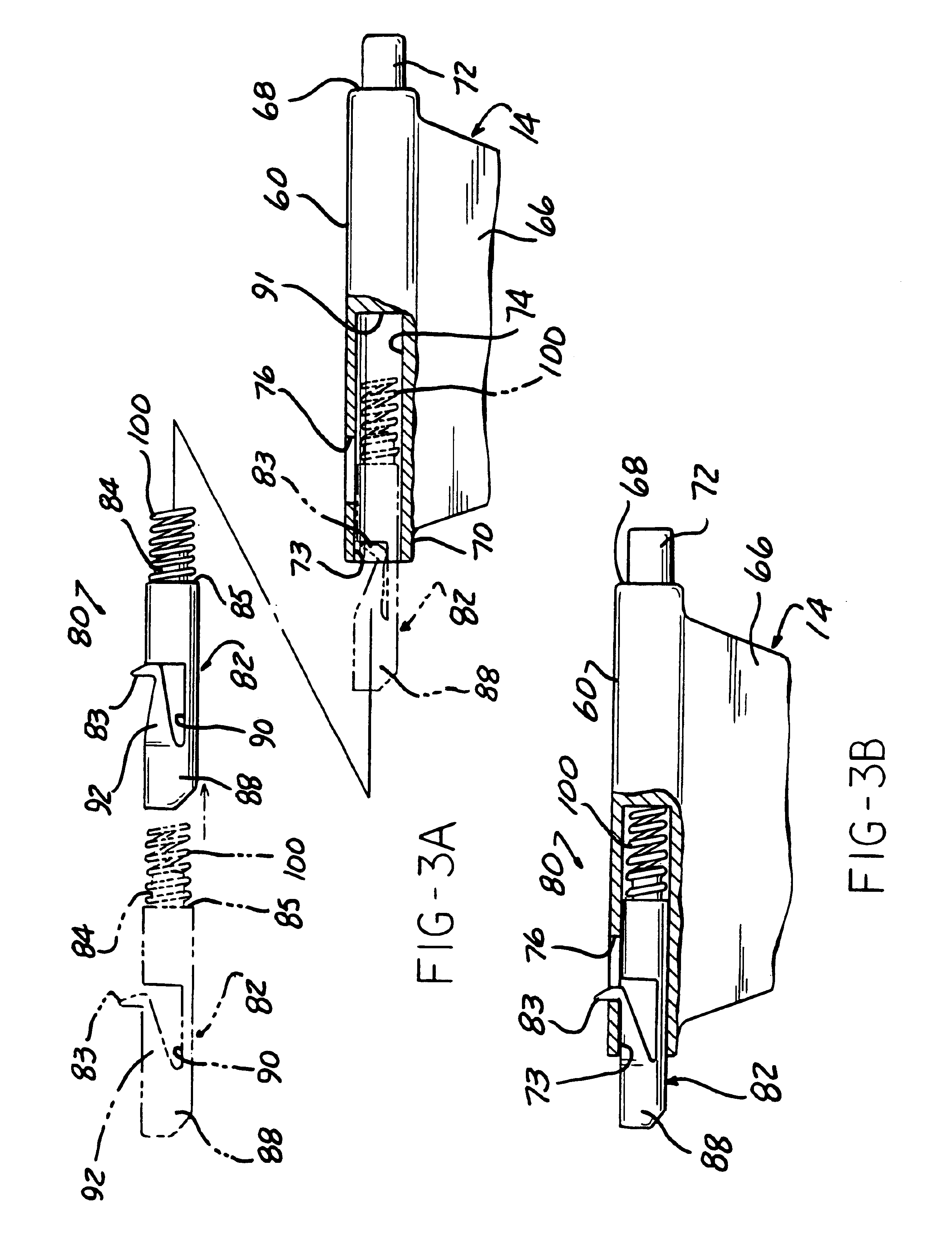
[0043]As shown in one aspect in FIGS. 1-4, the paddle 12 is formed of a generally planar plate 20 having one of a number of different configurations or sizes. The plate 20 is preferably formed of a lightweight ma...


PUM


Abstract

A cleaning apparatus and system includes at least one handle, at least one paddle, and at least one cleaning element. The handle is a pivotally attachable to each paddle. The cleaning element has elastic to draw the side edges of the body inward to form an opening smaller than the outer diameter of the paddle to releasably attach the cleaning element about the paddle. A receiver is mounted on each paddle and movably receives one end of the handle.

Description

CROSS REFERENCE TO CO-PENDING APPLICATION[0001]This application is a division of U.S. patent application Ser. No. 09 / 629,721, filed Jul. 31, 2000, now U.S. Pat. No. 6,169,153 issued Aug. 30, 2004, which is a continuation-in-part of application Ser. No. 09 / 104,957, filed on Jun. 25, 1998, now U.S. Pat. No. 6,178,584, issued Jan. 30, 2001, the entire contents of which are incorporated herein by reference.BACKGROUND[0002]1. Field of the Invention[0003]The present invention relates, in general, to cleaning apparatus and more specifically, to apparatus for cleaning vehicle windows.[0004]2. Description of the Art[0005]Various tools are available to clean the exterior surface of vehicle windows. Such tools typically include a handle and a perpendicularly oriented cleaning element, such as a wiper blade, sponge rubber pad and combinations thereof. Water or ammonia based cleaning fluid is applied to the exterior surface of the vehicle window and scraped off by the tools to remove debris. Suc...

Claims


Application Information

Patent Timeline
IPC IPC(8): A47L1/15A47L1/00A47L13/20B25G3/00B25G3/38
CPCA47L1/15A47L13/20B25G3/38
Inventor POST, KENNETH P.LASKOS, ROBERT
Owner K & R IND
Features
  • Generate Ideas
  • Intellectual Property
  • Life Sciences
  • Materials
  • Tech Scout
  • Unparalleled Data Quality
  • Higher Quality Content
  • 60% Fewer Hallucinations
Learn More