Steering apparatus

a technology of steering apparatus and guiding body, which is applied in the direction of steering parts, vehicle components, transportation and packaging, etc., can solve the problems of increasing the number of parts and increasing the cost of assembling operations, and achieves the effect of increasing the tightening force increasing the stability of the inner column sliding support, and increasing the rigidity of the main holding body portion

Active Publication Date: 2010-09-30
YAMADA SEISAKUSHO KK
View PDF7 Cites 19 Cited by
  • Summary
  • Abstract
  • Description
  • Claims
  • Application Information

AI Technical Summary

Benefits of technology

[0023]Thus, as described above, by forming the divided portion that is entirely divided along the axial direction, it is possible to bring the two tightening plate-like pieces at both ends in the widthwise direction (horizontal diametrical direction of the outer column) of the divided portion closer to each other in a parallel state thereof, without displacement. As a result, the outer column can be fixed to the inner column uniformly over the entire range from the axially front side to the axially rear side, the columns can be fixed with higher stability, and the tightening force thereof can be further increased.
[0024]In accordance with the invention as in claim 4, the divided portion is formed from one end side to the other end side in the axial direction of the main holding body portion except for a portion of the main holding body portion, and a circumferential support portion with an inner wall surface continuous in the circumferential direction is formed at the front end portion in the axial direction of the main holding body portion. As a result, the rigidity in sliding support of the inner column by the main holding body portion in the outer column can be increased, a portion of the inner column that is positioned in the open cavity portion is supported by an annular frame body constituted by the front circumferential support portion, arm portions, and linking portion, strain

Problems solved by technology

The resultant drawback is that the increase in the num

Method used


Image

  • Steering apparatus
  • Steering apparatus
  • Steering apparatus

Examples


Embodiment Construction

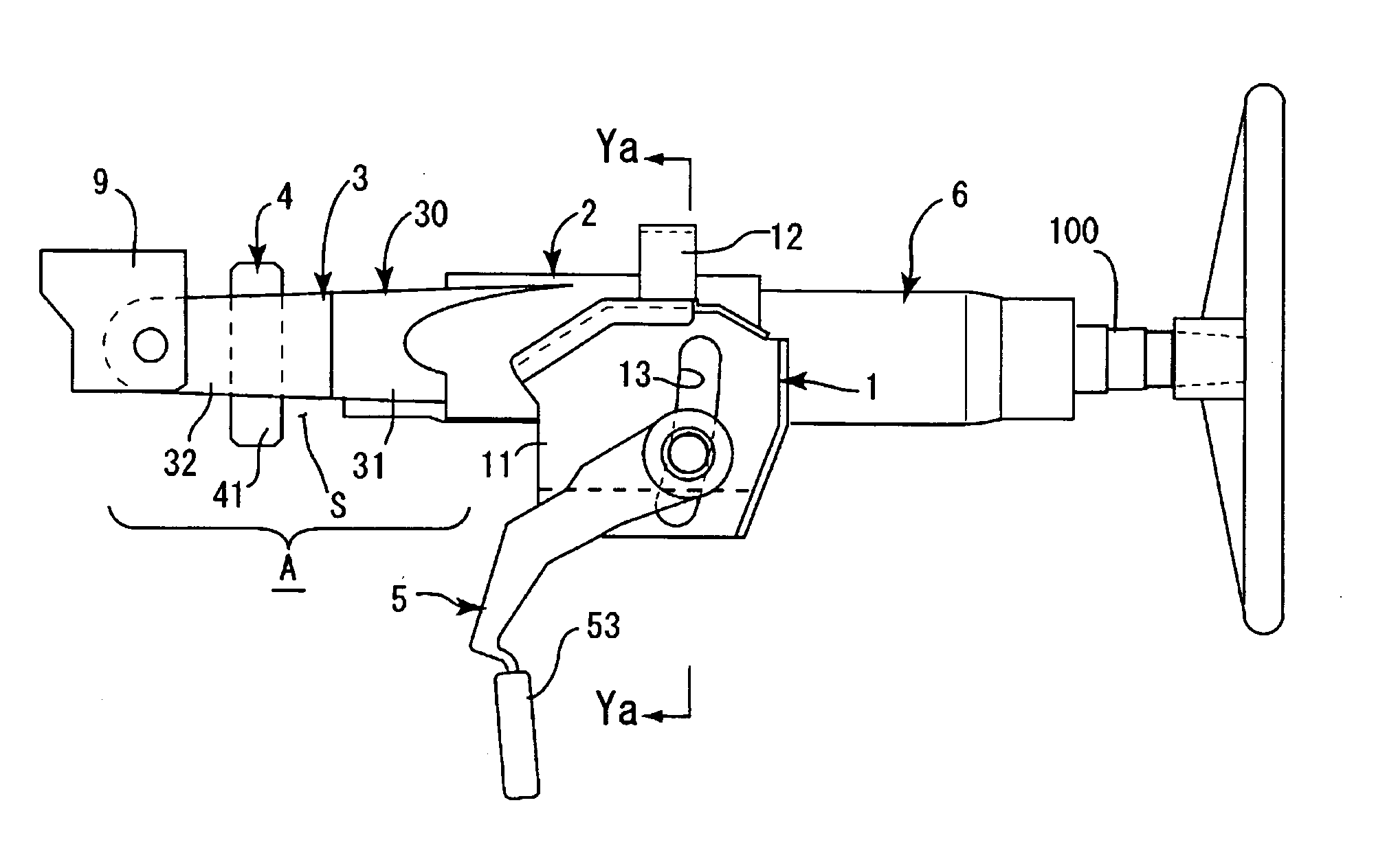
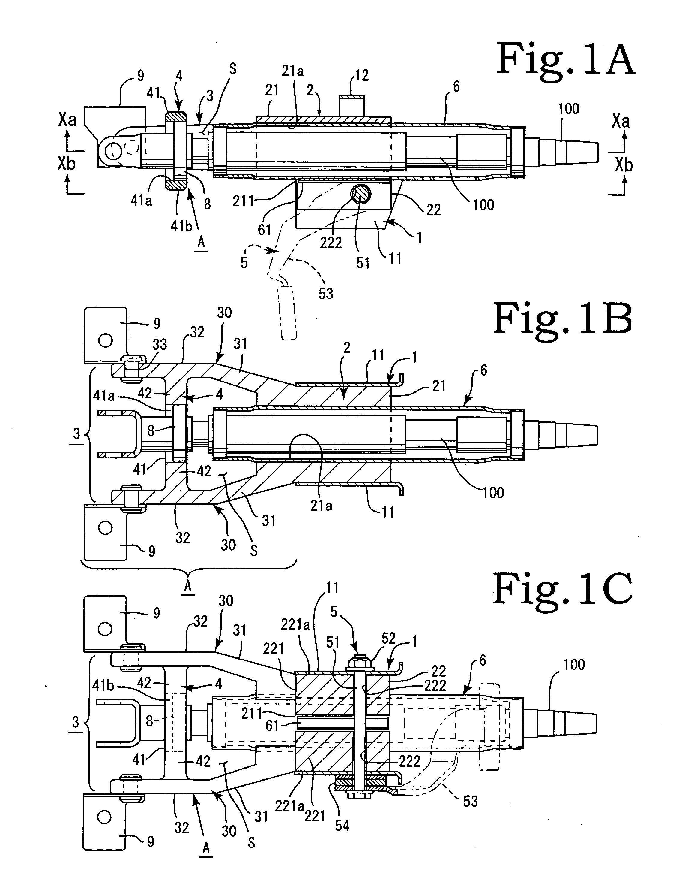
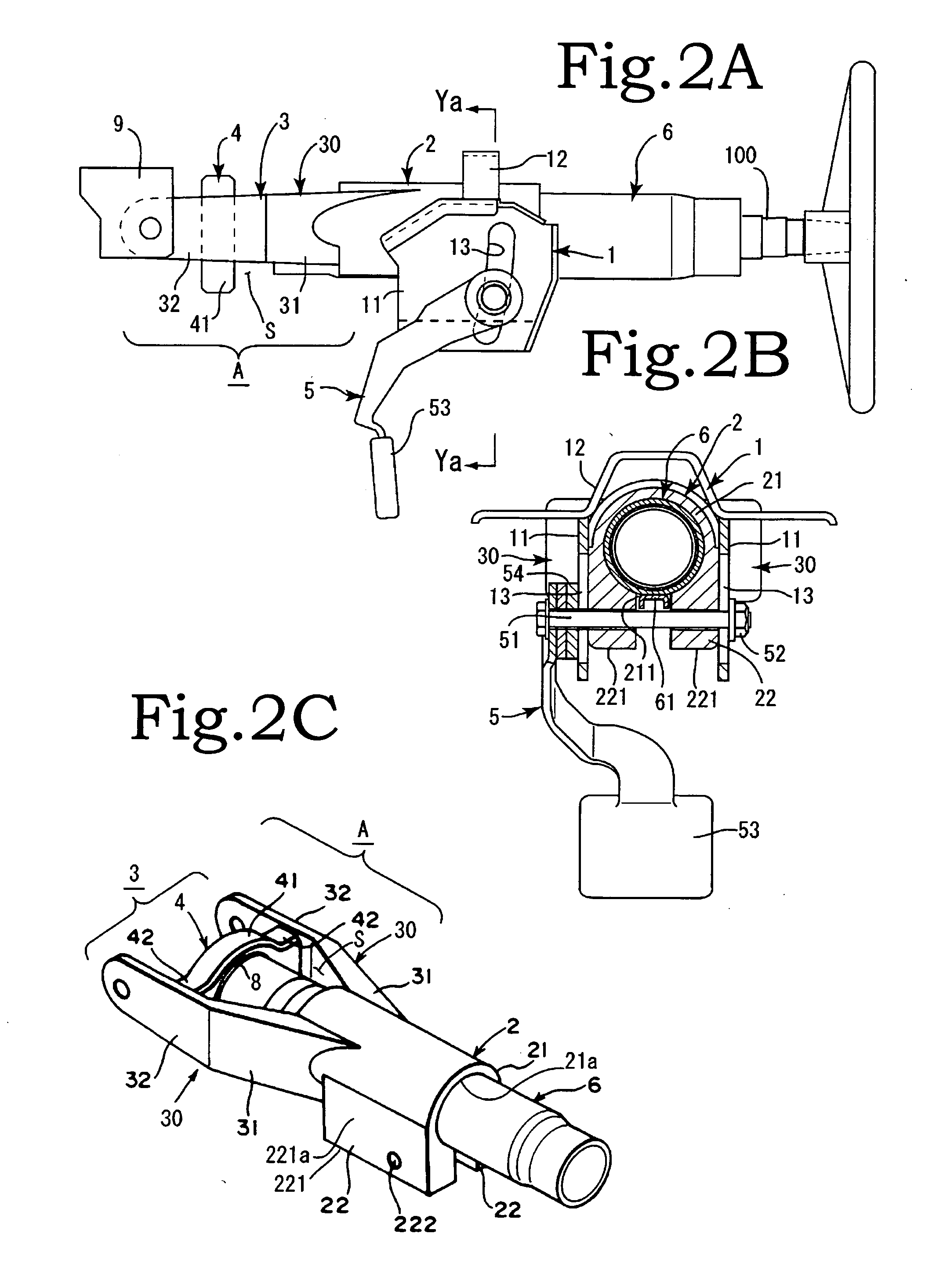
[0037]Embodiments of the present invention will be described below with reference to the appended drawings. As shown in FIG. 1 and FIG. 2, a principal configuration in accordance with the present invention includes a fixed bracket 1, an outer column 2 that is swingably mounted on the fixed bracket 1, an arm unit A, a tightening tool 5, an inner column 6, and a steering shaft 100. The fixed bracket 1 is constituted by fixed side portions 11, 11 formed at both sides in the widthwise direction and an attachment top portion 12. Adjustment holes 13, 13 that extend in a substantially up-down direction or vertical direction are formed in the two fixed size portion 11, 11 (see FIG. 2A). The attachment top portion 12 is mounted on a predetermined position inside a vehicle, with a capsule member being interposed therebetween, and can absorb impact energy during collision.

[0038]As shown in FIG. 2C and FIG. 3, the arm unit A is constituted by a bifurcated arm portion 3 and a linking portion 4. ...


PUM


Abstract

The present invention provides a steering apparatus which has increased rigidity in a fixed state of the steering column after positioning performed by tilt and telescopic adjustment, and in which a play is inhibited and operation feeling of steering is improved. The steering apparatus includes a fixed bracket, an outer column, an arm unit, an inner column, a steering shaft, and a tightening tool. The outer column is constituted by a main holding body portion, a divided portion, and a tightening portion. The arm unit is constituted by a bifurcated arm portion that extends axially outward in a substantially bifurcated shape at the axial front side of the main holding body portion and a linking portion formed between the arms of the bifurcated arm portion. The inner column is held by the outer column. The steering shaft is pivotally supported by the linking portion. Two tightening plate-like pieces of the tightening portion are disposed inside two fixed side portions of the fixed bracket and tightenably connected by the tightening tool.

Description

BACKGROUND OF THE INVENTION[0001]1. Technical Field[0002]The present invention relates to a steering apparatus which has increased rigidity in a fixed state of a steering column after positioning performed by tilt and telescopic adjustment and in which a play is inhibited and operation feeling of steering is improved.[0003]2. Description of the Related Art[0004]There are various steering apparatuses equipped with a tilt and telescopic adjustment mechanism. One of the typical structures of such steering apparatus is constituted by a fixed bracket mounted on a vehicle side, an inner column that rotatably supports a steering shaft, a steering support body that axially slidably supports the inner column, and a tightening means for tightening the inner column via the steering support body by tightening the fixed bracket.[0005]It is especially important that the steering apparatus have good rigidity at the time of fixing in the correct position after the respective correct position has be...

Claims


Application Information

Patent Timeline
IPC IPC(8): B62D1/187B62D1/18B62D1/184
CPCB62D1/189B62D1/184
Inventor TAKEZAWA, NAOYUKISATOU, YOSHIYUKI
Owner YAMADA SEISAKUSHO KK
Why Eureka
Try Eureka