Eyeglass-type image display device and an eyeglass frame used therefor

a display device and eyeglass frame technology, applied in the field of eyeglass-type image display device and eyeglass frame used therefor, can solve the problems of increasing the load applied to the nose and ears of users, increasing the cost, and impairing the aesthetic look of eyeglasses, so as to reduce the cost, improve the aesthetic look, and reduce the effect of weigh

Active Publication Date: 2010-09-30
OLYMPUS CORP
View PDF2 Cites 11 Cited by
  • Summary
  • Abstract
  • Description
  • Claims
  • Application Information

AI Technical Summary

Benefits of technology

[0018]According to the eyeglass-type image display device in accordance with the present invention, the light guiding unit that guides the image light from the display element is disposed on the limb unit of the eyeglass frame so as to be displaceable to the first position where the light guiding unit is evacuated from the front of the eyeball and to a second position where the light guiding unit extends to the front of the eyeball and the image light can exit therethrough toward the eyeball, thereby making the structure simple, compact and light weight, which enables cost reduction and does not impair the aesthetic look as a pair of eyeglasses, and further enables the user to wear the pair of eyeglasses for a long period of time with ease without feeling that the pair of eyeglasses is heavy.
[0019]Further, according to the eyeglass frame in accordance with the present invention, it is possible to provide an eyeglass frame that can constitute an eyeglass-type image display device that produces the aforementioned operations and effects easily.

Problems solved by technology

Consequently, there is concern that a device becomes large scale, thereby causing an increase in the cost.
In addition, in the case where the image display unit is located on the standby position, there is concern that the user feels the image display unit, the guide rail and the like as eyesores and that when seeing from the third person, the body unit, the image display unit and the like project greatly from the eyeglass frame, which may impair the aesthetic look as a pair of eyeglasses.
Further, increased weight may increase the load applied to the nose and ears of the user when he / she wears the pair of eyeglasses, thereby making it difficult for the user to wear the pair of eyeglasses for a long period of time.

Method used


Image

  • Eyeglass-type image display device and an eyeglass frame used therefor
  • Eyeglass-type image display device and an eyeglass frame used therefor
  • Eyeglass-type image display device and an eyeglass frame used therefor

Examples


first embodiment

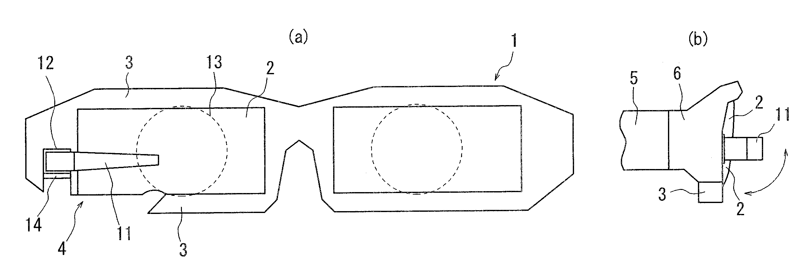
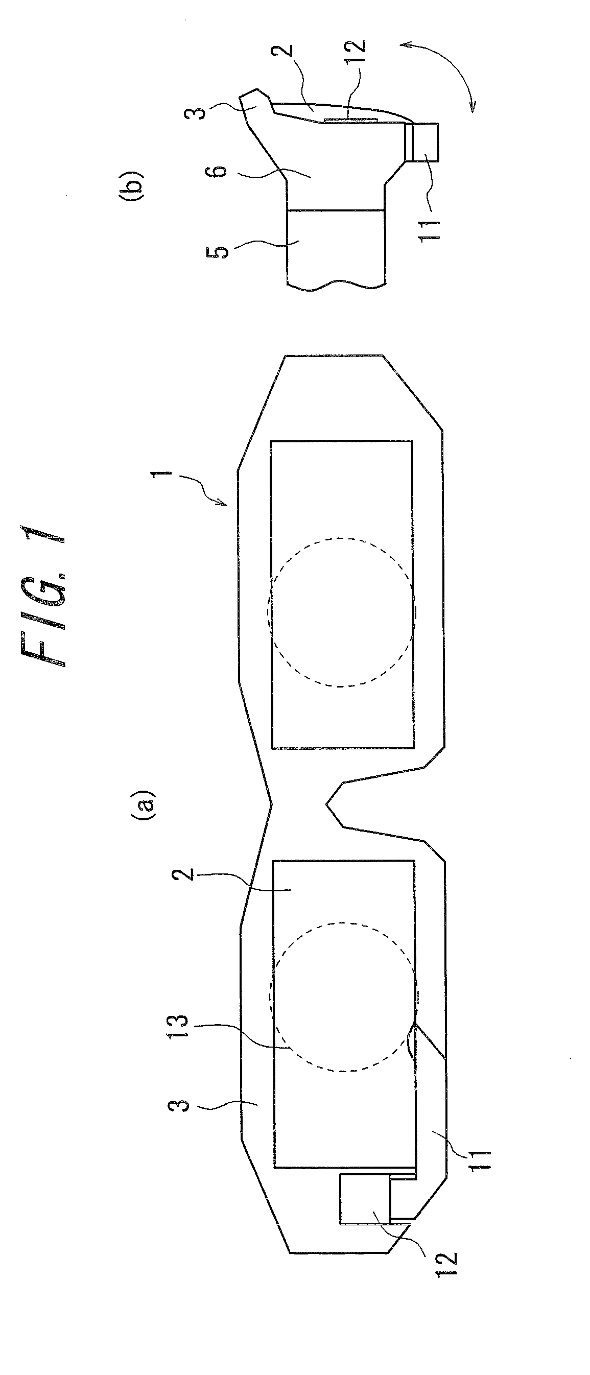
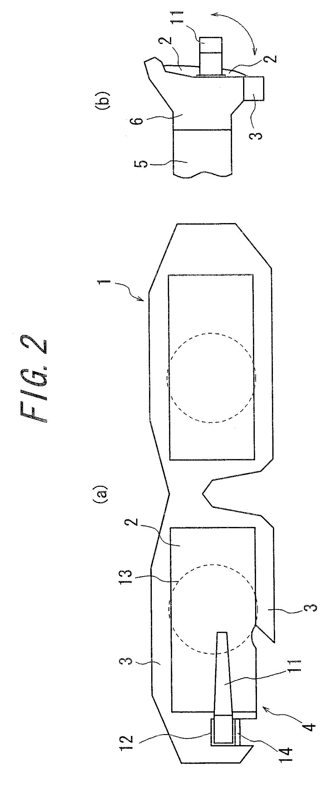
[0036]FIGS. 1 to 3 show a schematic diagram of an eyeglass-type image display device in accordance with a first embodiment of the present invention. FIGS. 1A and 1B are an elevation view and a side view showing an image non-observing state where image observation is not performed and FIGS. 2A and 2B an elevation view and a side view showing an image observable state where the image observation is possible, and FIGS. 3A to 3C are a partial schematic view.

[0037]The eyeglass-type image display device in accordance with the present embodiment is a right-eye type and has a light guiding unit 11 that is provided on a limb unit 3 for a right eye for holding a lens 2 for a right eye of the eyeglass frame 1. The light guiding unit 11 is constituted by plastic, glass and the like and one end thereof is rotatably held by the central portion of the outer lateral side of the limb unit 3 via a holding member 12 so that it selectably extends to the notch part 4 that is formed from the central port...

second embodiment

[0046]FIGS. 4 to 6 show a schematic diagram of an eyeglass-type image display device in accordance with a second embodiment of the present invention. FIGS. 4A and 4B show respectively an elevation view and a side view of the image non-observing state, FIGS. 5A and 5B show respectively an elevation view and a side view of the image observable state and FIGS. 6A and 6B show a partial schematic diagram corresponding to FIGS. 3A and 3B.

[0047]In the eyeglass-type image display device in accordance with the present embodiment, relative to the first embodiment, the notch part 4 is formed from the central portion of the upper part along to a portion of the outer lateral side of the limb unit 3, and the light guiding unit 11 is rotatably held to the limb unit 3 so that the light guiding unit 11 selectably extends to the notch part 4. Since the other structures are the same as those of the first embodiment, the same reference numbers are assigned to the same components and explanations thereo...

third embodiment

[0049]FIGS. 7 to 9 show a schematic diagram of an eyeglass-type image display device in accordance with a third embodiment of the present invention. FIGS. 7A and 7B show respectively an elevation view and a side view of the image non-observing state, FIGS. 8A and 8B show respectively an elevation view and a side view of the image observable state and FIGS. 9A and 9B show a partial schematic diagram.

[0050]In the eyeglass-type image display device in accordance with the present embodiment, the appearance shape of the limb unit 3 is curved compared to the first embodiment. Thus, in the present embodiment, the light guiding unit 11 is formed in an appearance shape that assumes curve in accordance with the appearance shape of the limb unit 3 so that the light guiding unit 11 forms a part of the outer shape of the limb unit 3 in the image non-observing state where the light guiding unit 11 is located on the first position shown in FIGS. 7A and 7B. Such curved light guiding unit 11 can be ...


PUM


Abstract

An eyeglass-type image display device mounted on an eyeglass frame and has a display element for displaying an image and a light guiding unit for guiding the image light of the image displayed on the display element 15 is provided, wherein at least the light guiding unit is disposed on a limb unit so as to be displaceable to a first position where the light guiding unit is evacuated from the front of one eyeball of the user and to the second position where the light guiding unit extends to the front of the eyeball and the image light exits therethrough toward the eyeball, thereby enabling compact and light-weight structure, reduction in cost, and further enabling the user to wear the eyeglass frame for a long time without feeling that the eyeglass frame is heavy.

Description

CROSS-REFERENCE TO RELATED APPLICATION[0001]The present application claims priority from Japanese Application No. 2009-074809 filed on Mar. 25, 2009, the content of which is incorporated herein by reference.FIELD OF THE INVENTION[0002]The present invention relates to an eyeglass-type image display device and an eyeglass frame used therefor.BACKGROUND OF THE INVENTION[0003]As disclosed by JP 2008-67285 A, for example, an eyeglass-type image display device that includes, for example, a body unit fixed to a temple of an eyeglass frame and an image display unit that is movable to a standby position adjacent to the body unit and to a use position immediately in front of an eyeglass lens, and causes the body unit to automatically move the image display unit to the standby position and to the use position is known.[0004]However, with respect to the aforementioned image display device disclosed by JP 2008-67285 A, in order to move the image display unit to the standby position and to the us...

Claims


Application Information

Patent Timeline
Patent Type & Authority Applications(United States)
IPC IPC(8): G02C11/00
CPCG02B27/0172G02B6/00
Inventor SUGIHARA, RYOHEITATSUTA, SEIJIIBA, YOICHITOMITA, TERUO
Owner OLYMPUS CORP
Why Eureka
Try Eureka