Abrasive tool for use as a chemical mechanical planarization pad conditioner

a technology of chemical mechanical and planarization pad, applied in the field of abrasive tools, can solve the problems of affecting the polishing of sensitive electronic components, affecting the polishing effect, and exhibiting less than optimal performan

Active Publication Date: 2010-09-30
SAINT GOBAIN ABRASIVES INC +1
View PDF98 Cites 69 Cited by
  • Summary
  • Abstract
  • Description
  • Claims
  • Application Information

AI Technical Summary

Problems solved by technology

A wafer surface that is not sufficiently planar will result in structures that are poorly defined, with the circuits being nonfunctional or exhibiting less than optimum performance.
Still, the conditioning operation faces certain obstacles, including the presenc

Method used


Image

  • Abrasive tool for use as a chemical mechanical planarization pad conditioner
  • Abrasive tool for use as a chemical mechanical planarization pad conditioner
  • Abrasive tool for use as a chemical mechanical planarization pad conditioner

Examples


Embodiment Construction

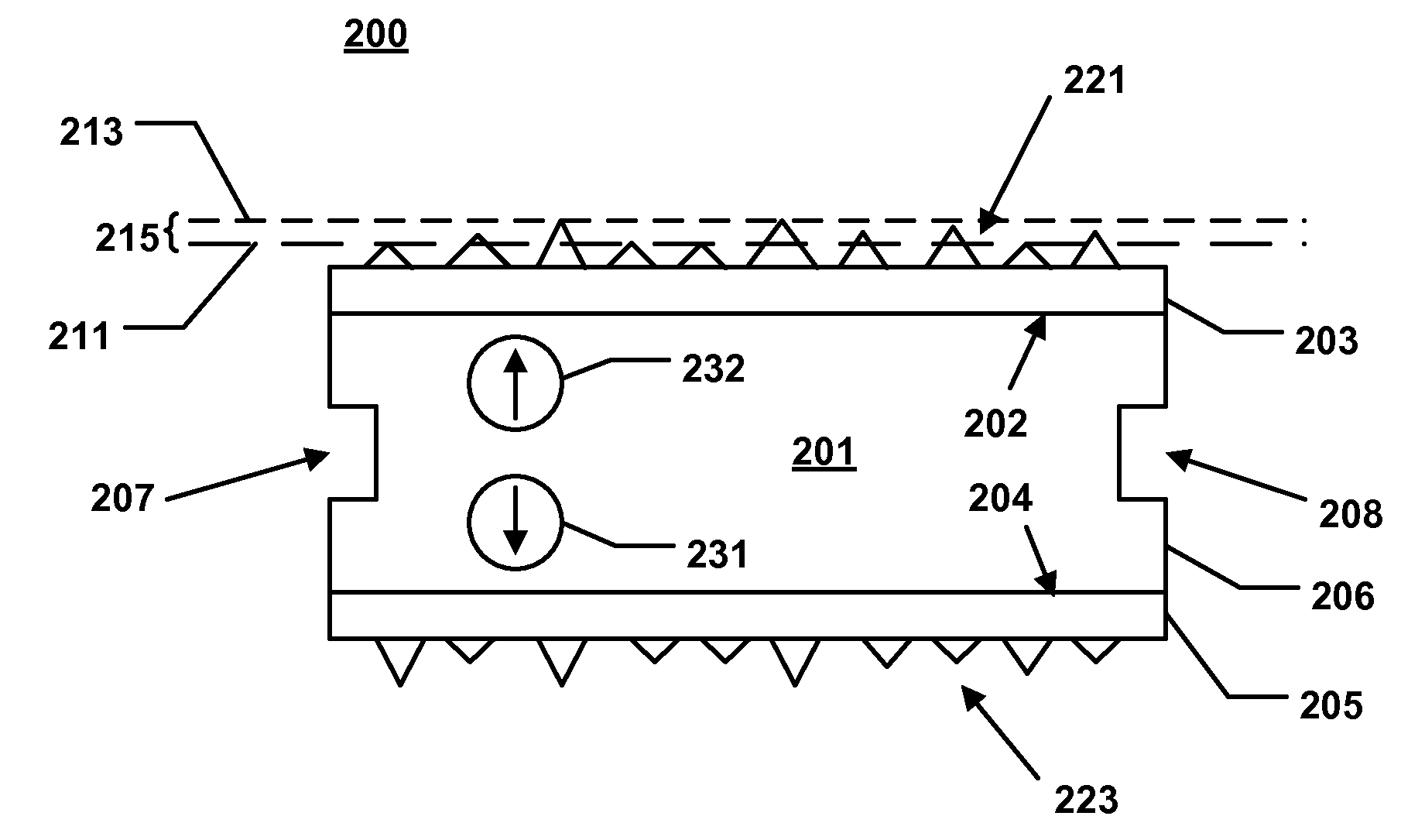
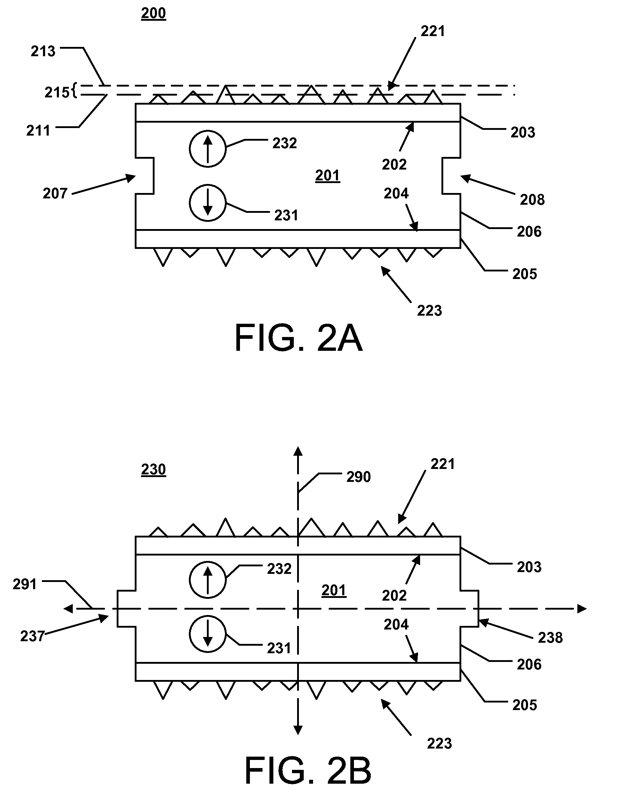
[0056]The following is directed to an abrasive tool for use as a chemical mechanical planarization (CMP) pad conditioner, also referred to as a dresser. The abrasive tool includes a plurality of features including an abrasive article having two (first and second) abrading surfaces and coupling mechanisms for removably coupling the abrasive article with a fixture or plate. The abrasive tool can include different types of engagement structures facilitating removal and reversing of the abrasive tool such that both first and second abrading surfaces are useable.

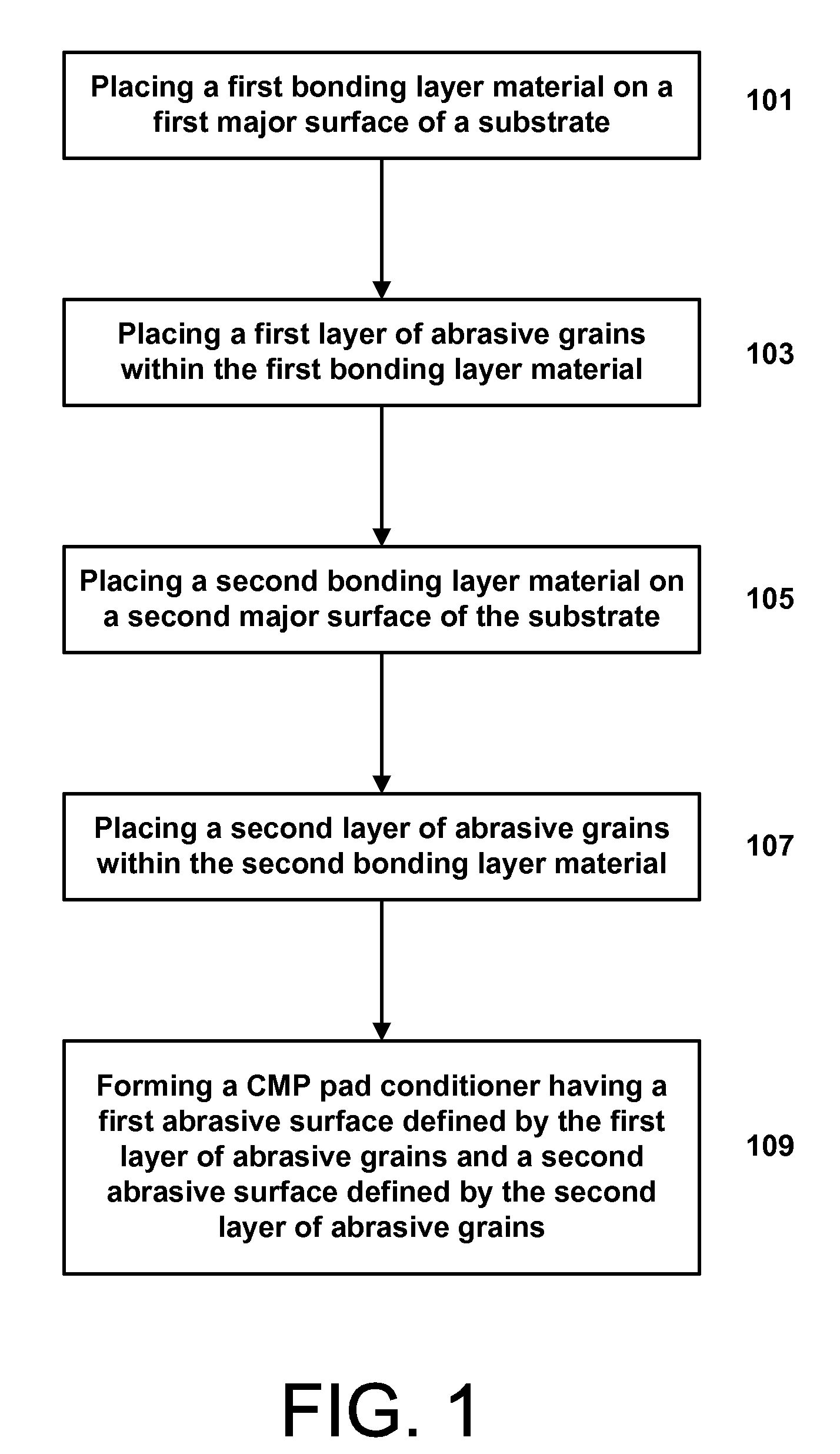
[0057]FIG. 1 includes a flowchart demonstrating a method of forming an abrasive tool in accordance with an embodiment. As illustrated, the process can be initiated at step 101 by placing a first bonding layer material on a first major surface of a substrate.

[0058]Generally, the substrate is made of a material suitable for withstanding the rigors of abrasive processing. For example, the substrate can be a material having an elasti...


PUM

PropertyMeasurementUnit
Sizeaaaaaaaaaa
Sizeaaaaaaaaaa
Abrasiveaaaaaaaaaa

Abstract

An abrasive tool including a CMP pad conditioner having a substrate including a first major surface, a second major surface opposite the first major surface, and a side surface extending between the first major surface and the second major, wherein a first layer of abrasive grains is attached to the first major surface and a second layer of abrasive grains is attached to the second major surface. The conditioner further includes a first sealing member extending in a peripheral direction along a portion of the side surface of the substrate.

Description

CROSS-REFERENCE TO RELATED APPLICATION(S)[0001]The present application claims priority from (i) U.S. Provisional Patent Application No. 61 / 162,893, filed Mar. 24, 2009, entitled “Abrasive Tool For Use As A Chemical Mechanical Planarization Pad Conditioner,” naming inventors Charles Dinh-Ngoc, Srinivasan Ramanath, Eric M. Schulz, Jianhui Wu, Thomas Puthanangady, Ramanujam Vedantham, and Taewook Hwang, and (ii) U.S. Provisional Patent Application No. 61 / 235,980, filed Aug. 21, 2009, entitled “Abrasive Tool For Use As A Chemical Mechanical Planarization Pad Conditioner,” naming inventors Charles Dinh-Ngoc, Srinivasan Ramanath, Eric M. Schulz, Jianhui Wu, Thomas Puthanangady, Ramanujam Vedantham, and Taewook Hwang, which applications are both incorporated by reference herein in their entiretyBACKGROUND[0002]1. Field of the Disclosure[0003]The following application is directed to an abrasive tool, and more particularly to an abrasive tool for use as a chemical mechanical planarization pa...

Claims


Application Information

Patent Timeline
IPC IPC(8): B24B53/02B24B53/12B24B37/04
CPCB24B37/04B24B53/12B24B53/017
Inventor DINH-NGOC, CHARLESRAMANATH, SRINIVASANSCHULZ, ERIC M.WU, JIANHUIPUTHANANGADY, THOMASVEDANTHAM, RAMANUJAMHWANG, TAEWOOK
Owner SAINT GOBAIN ABRASIVES INC
Why Eureka
Try Eureka