Vehicle Dynamics Control Device

a technology of vehicle dynamics and control device, which is applied in the direction of braking system, instruments, analogue processes for specific applications, etc., can solve the problems of poor drivability during automatic deceleration, insufficient ease of use, poor handling, etc., and achieves a high level of drivability

Inactive Publication Date: 2010-09-30
HITACHI LTD
View PDF7 Cites 55 Cited by
  • Summary
  • Abstract
  • Description
  • Claims
  • Application Information

AI Technical Summary

Benefits of technology

[0009]The present invention, having been achieved by addressing the issues discussed above, provides a vehicle dynamics control device capabl

Problems solved by technology

However, after the control is terminated upon detecting a skid, the driver will need to induce the required deceleration on his own immediately and thus, a sufficient level of ease of use is not assured by the device.
In addition, when a lock-up at the wheels that would otherwise occur under automatic deceleration control is disallowed via an antilock braking system, excessive skidding occurs immediately b

Method used


Image

  • Vehicle Dynamics Control Device
  • Vehicle Dynamics Control Device
  • Vehicle Dynamics Control Device

Examples


first embodiment

[0061]In reference to FIGS. 9 through 15, the structure of the vehicle dynamics control device achieved in the first embodiment of the present invention and the operation executed therein are described.

[0062]First, in reference to FIG. 9, the structure adopted in the vehicle dynamics control device in the first embodiment of the present invention is described.

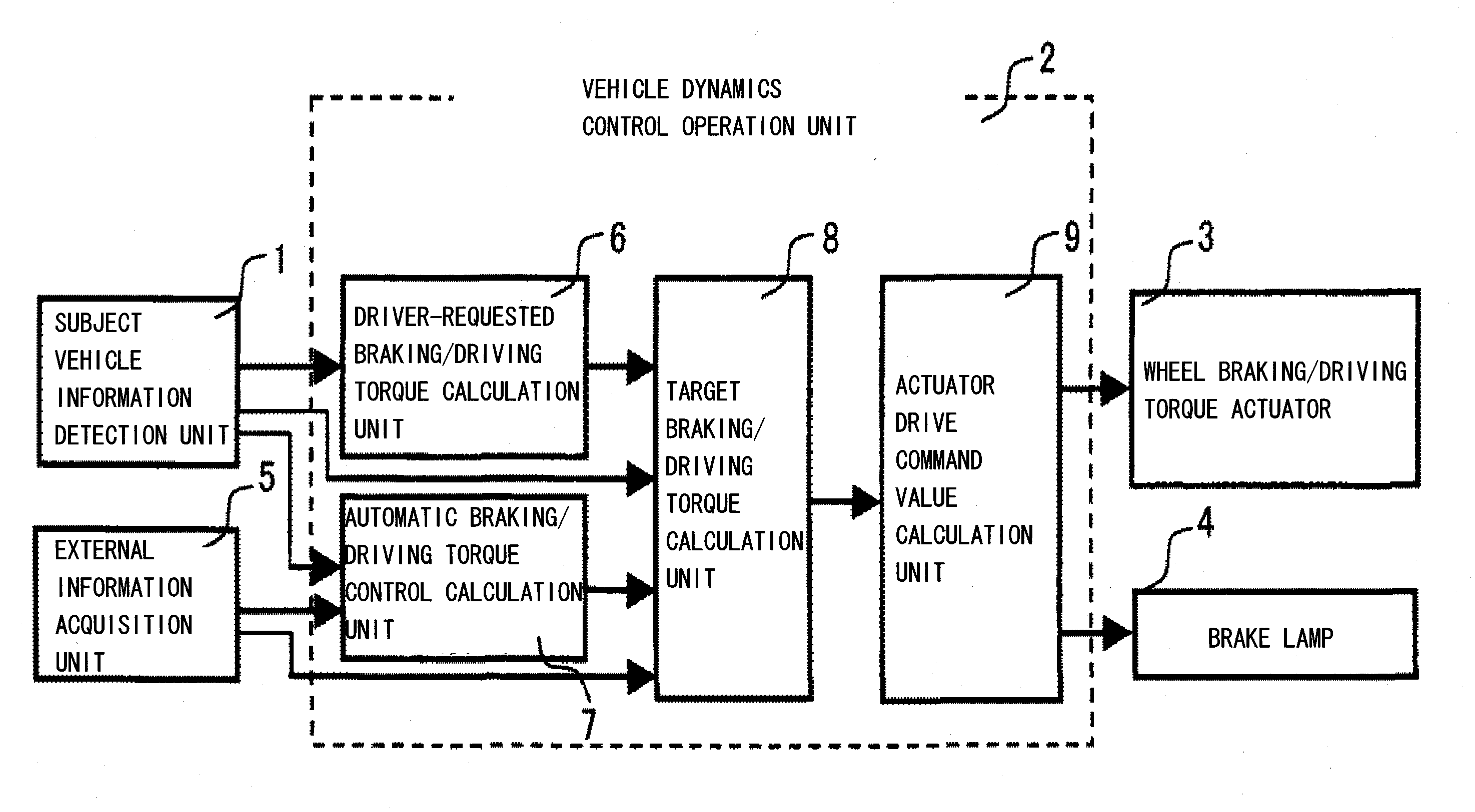
[0063]FIG. 9 is a system block diagram showing the structure of the vehicle dynamics control device achieved in the first embodiment of the present invention.

[0064]The vehicle dynamics control device achieved in the embodiment, which is installed in a vehicle, includes a subject vehicle information detection unit 1 that obtains information indicating subject vehicle dynamics conditions and an operation quantity representing the extent to which the subject vehicle is operated by the driver, a vehicle dynamics control operation unit 2 that provides control commands to braking / driving force actuators and the like, a wheel braking / ...

second embodiment

[0111]In reference to FIGS. 16 and 17, the structure adopted in the vehicle dynamics control device achieved in the second embodiment of the present invention and the operation executed therein are described.

[0112]First, in reference to FIG. 16, the structure adopted in the vehicle dynamics control device in the second embodiment of the present invention is described.

[0113]FIG. 16 is a system block diagram showing the structure of the vehicle dynamics control device achieved in the second embodiment of the present invention.

[0114]The vehicle dynamics control device achieved in the embodiment, which is installed in a vehicle, includes a subject vehicle information detection unit 1 that obtains information indicating subject vehicle dynamics conditions and an operation quantity representing the extent to which the subject vehicle is operated by the driver, a vehicle dynamics control operation unit 2′ that provides control commands to braking / driving force actuators and the like, a whe...

third embodiment

[0123]In reference to FIGS. 18 through 20, the structure of the vehicle dynamics control device achieved in the third embodiment of the present invention and the operation executed therein are described.

[0124]First, in reference to FIG. 18, the structure adopted in the vehicle dynamics control device in the third embodiment of the present invention is described.

[0125]FIG. 18 is a system block diagram showing the structure of the vehicle dynamics control device achieved in the third embodiment of the present invention.

[0126]The vehicle dynamics control device achieved in the embodiment, which is installed in a vehicle, includes a subject vehicle information detection unit 1 that obtains information indicating a subject vehicle dynamics conditions and an operation quantity representing the extent to which the subject vehicle is operated by the driver, a vehicle dynamics control operation unit 2″ that provides control commands to braking / driving force actuators and the like, a wheel br...


PUM


Abstract

A vehicle dynamics control device includes: a control unit that executes braking/driving torque control for controlling at least either a braking torque or a driving torque at each wheel based upon at least either external information pertaining to an environment of a vehicle or vehicle information that includes operation input information indicating an operation input by a driver and a vehicle dynamics information. And the operation input information includes a lateral motion operation index pertaining to a lateral motion operation executed to generate a lateral motion in the vehicle; the vehicle dynamics information includes a longitudinal acceleration generated in the vehicle and a lateral motion index indicating a lateral motion occurring in the vehicle; and the control unit determines a handling assurance acceleration limit with a maximum longitudinal acceleration value that assumes a substantially linear proportional relationship with the lateral motion operation index and the lateral motion index over a range in which the lateral motion operation index assumes a value equal to or less than a predetermined value or the lateral motion index assumes a value equal to or less than a predetermined value, and executes the braking/driving torque control by setting the handling assurance acceleration limit as an upper limit to a longitudinal acceleration to be generated in the vehicle under the braking/driving torque control.

Description

INCORPORATION BY REFERENCE[0001]The disclosure of the following priority application is herein incorporated by reference: Japanese Patent Application No. 2009-080852 filed Mar. 30, 2009BACKGROUND OF THE INVENTION[0002]1. Field of the Invention[0003]The present invention relates to a vehicle dynamics control device that controls the braking force and the driving force imparted to each wheel so as to achieve an optimal state of vehicle dynamics.[0004]2. Description of Related Art[0005]There are devices known in the related art that slow the subject vehicle so as to achieve an optimal speed for avoiding a collision with an obstacle present ahead of the subject vehicle or for traveling along a curve ahead of the subject vehicle through an automatic downshift or an automatic brake engagement in correspondence to the particular obstacle or curve (see, for instance, Japanese Laid Open Patent Publication No. H6-36187 and Japanese Laid Open Patent Publication No. H10-269499). While such a de...

Claims


Application Information

Patent Timeline
IPC IPC(8): G06F19/00B60W10/00B60W30/00B60W30/02
CPCB60T8/1755B60T2270/613B60W30/00B60W10/04B60W10/18B60W30/045
Inventor TAKAHASHI, JUNYAYAMAKADO, MAKOTOYOKOYAMA, ATSUSHISAITO, SHINJIRO
Owner HITACHI LTD
Why Eureka
Try Eureka