Lane fusion system using forward-view and rear-view cameras

a technology of rearview camera and fusion system, which is applied in the field of vehicle lane position method and system, can solve the problems of inability to operate systems relying on the image of the camera for input, preventing a good image from being obtained from the forward-viewing camera, and obscuring the image of the camera

Active Publication Date: 2012-03-15
GM GLOBAL TECH OPERATIONS LLC
View PDF17 Cites 64 Cited by
  • Summary
  • Abstract
  • Description
  • Claims
  • Application Information

AI Technical Summary

Problems solved by technology

However, conditions may arise which prevent a good image from being obtained from the forward-viewing camera.
Such conditions include a leading vehicle at close range which blocks much of the camera's field of view, and low-visibility weather conditions, such as rain and fog, which obscure the camera's image.
In such conditions, when a usable image from the forward-view camera is not available, systems which rely on the camera's image for input cannot be operated.
Although these rear-view cameras typically have a resolution and field of view which are more than sufficient for other image data collection purposes, until now they have not been used to supplement the images from forward-view cameras for lane position and lateral control applications.

Method used


Image

  • Lane fusion system using forward-view and rear-view cameras
  • Lane fusion system using forward-view and rear-view cameras
  • Lane fusion system using forward-view and rear-view cameras

Examples


first embodiment

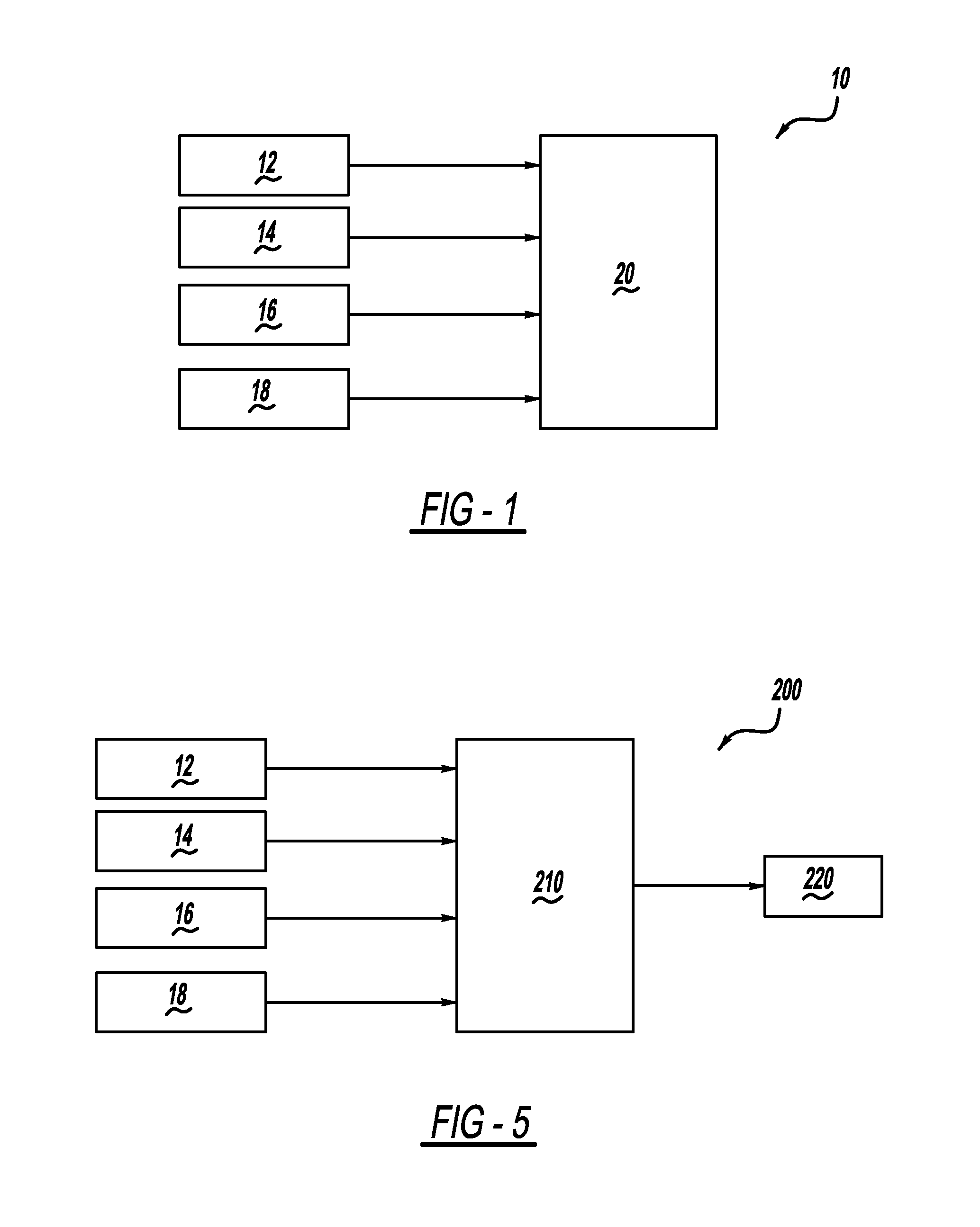
[0064]FIG. 6 is a block diagram of a lane fusion system 240 using input from two cameras. In the system 240, a full-fledged forward lane sensor system 242 and a full-fledged rear lane sensor system 244 each include a camera and a processor, and can detect and track lane boundaries at their respective ends of the host vehicle 50. The forward lane sensor system 242 and the rear lane sensor system 244 provide their measurements to a lane fusion module 246 which computes enhanced lane boundary and orientation information. The forward lane sensor system 242 sends measurements θF, ΔyF, and κ to the fusion module 246 at a fixed sample rate (e.g., 10 Hz). The rear lane sensor system 244 sends measurements θT and ΔyT at the same fixed sample rate. The forward lane sensor system 242, the rear lane sensor system 244, and the fusion module 246 are interconnected by a serial network 248, which may use the Control Area Network (CAN) or other protocol.

[0065]The fusion module 246 takes inputs from ...

second embodiment

[0077]FIG. 7 is a block diagram of a lane fusion system 300 using input from two cameras. The system 300 does not include full-fledged lane sensor systems at the front and rear. Instead, the system 300 includes a forward-view camera 302 and a rear-view camera 304. The cameras 302 and 304 only capture images and send them to a fusion module 320, which combines both images together, detects and tracks the lane markers.

[0078]Images from the forward-view and rear-view cameras 302 and 304, respectively, are provided to box 306 to find local high intensity regions. The key idea of the box 306 is to find stable local high-intensity regions in different spatial scales. The algorithm begins with building a Gaussian pyramid. At each pyramid scale, the image is subtracted by the enlarged coarse-level image, which is further blurred. Then the local maximum finding operation is applied to the difference images at different scales, and all maxima whose height is less than a threshold h are suppre...


PUM


Abstract

A method and system for computing lane curvature and a host vehicle's position and orientation relative to lane boundaries, using image data from forward-view and rear-view cameras and vehicle dynamics sensors as input. A host vehicle includes cameras at the front and rear, which can be used to detect lane boundaries such as curbs and lane stripes, among other purposes. The host vehicle also includes vehicle dynamics sensors including vehicle speed and yaw rate. A method is developed which computes lane curvature and the host vehicle's position relative to a lane reference path, where the lane reference path is derived from the lane boundaries extracted from a fusion of the front and rear camera images. Mathematical models provided in the disclosure include a Kalman filter tracking routine and a particle filter tracking routine.

Description

BACKGROUND OF THE INVENTION[0001]1. Field of the Invention[0002]This invention relates generally to a lane position method and system for a vehicle and, more particularly, to a lane position method and system for a host vehicle which uses a fusion of image data from forward-view and rear-view cameras and data from vehicle dynamics sensors to compute lane parameters, including lane curvature and the host vehicle's position and orientation relative to a lane reference path.[0003]2. Discussion of the Related Art[0004]Many modern vehicles include onboard cameras, which are used for a variety of purposes. One common application is a forward-viewing camera which can provide images to be used in a collision avoidance system, a lane departure warning system, a lateral control system, or a combination of these or other systems. However, conditions may arise which prevent a good image from being obtained from the forward-viewing camera. Such conditions include a leading vehicle at close range...

Claims


Application Information

Patent Timeline
Patent Type & Authority Applications(United States)
IPC IPC(8): H04N7/18
CPCB60W40/06G06K9/00798B60W2550/146B60W2552/30G06V20/588
Inventor ZENG, SHUQING
Owner GM GLOBAL TECH OPERATIONS LLC
Why Eureka
Try Eureka