Electric rotary machine
a technology rotary machines, which is applied in the direction of electric devices, magnetic circuit shapes/forms/construction, transportation and packaging, etc., can solve the problems of increasing iron loss of electric rotary machines, and achieve the effect of reducing iron loss
- Summary
- Abstract
- Description
- Claims
- Application Information
AI Technical Summary
Benefits of technology
Problems solved by technology
Method used
Image
Examples
embodiment 1
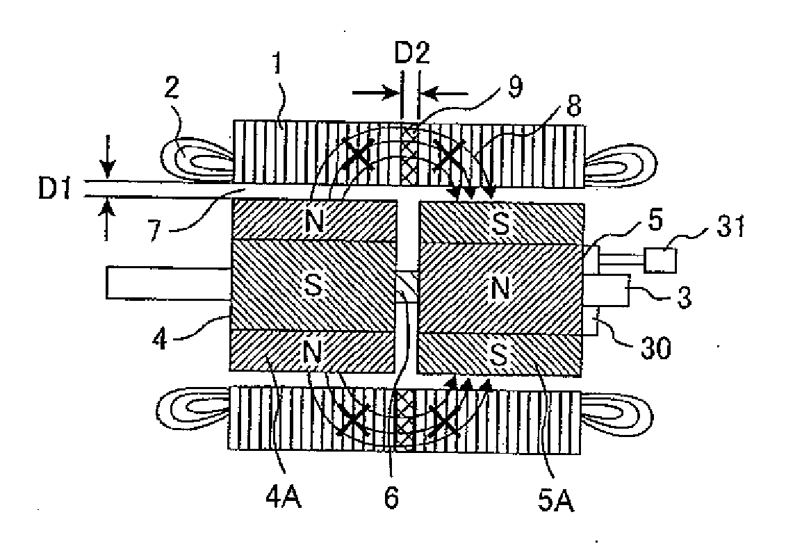
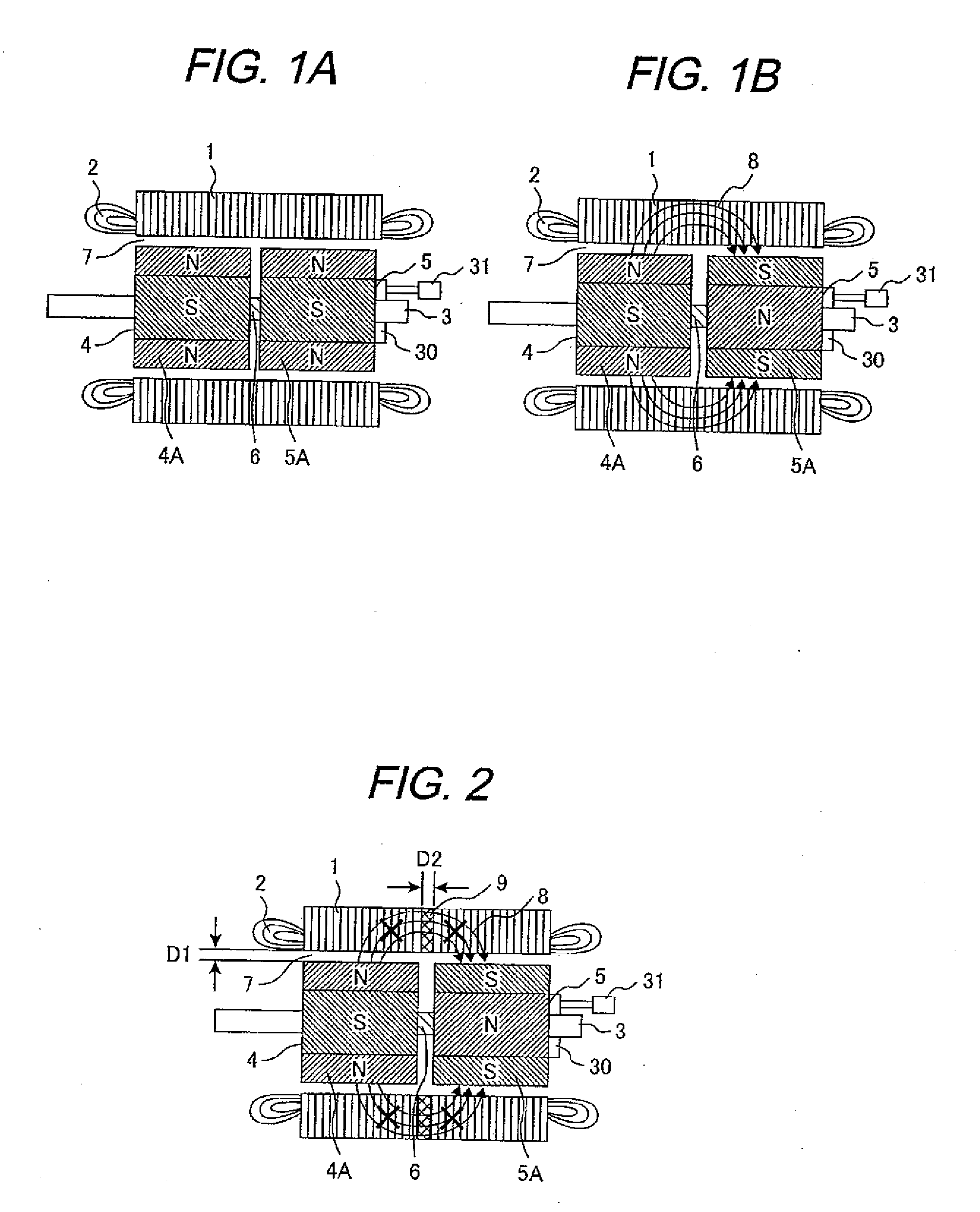
[0030]Next, an embodiment of the present invention will be explained referring to FIG. 2. Incidentally, the embodiment of FIG. 2 has the same structure and effect as those of FIGS. 1A and 1B other than the following magnetoresistive layer 9. FIG. 2 shows an alignment of permanent magnets 4A and 5A of the first and second rotors 4 and 5 corresponding to that of FIG. 1B. As shown in FIG. 1B, the stator core 1 of the electric rotary machine is provided with a doughnut-shaped magnetoresistive layer 9 (of thickness: D2) in the path of the effective magnetic fluxes in the stator core 1, so that the stator core 1 is divided into two in the axis direction thereof by the doughnut-shaped magnetoresistive layer 9. Namely, the magnetoresistive layer 9 is interposed between the divided stator cores. Herein, in order to interrupt the magnetic flux flow 8, it is desirable that the magnetic resistance of the magnetoresistive layer 9 in the stator core 1 is higher than the magnetic resistance of the...
embodiment 2
[0034]Another embodiment of an electric rotary machine according to the present invention will be explained based on FIG. 3. Herein below, the same parts as in the previous embodiment are denoted with the same reference numerals and the explanation thereof is omitted, and only the parts different from the previous ones will be explained.
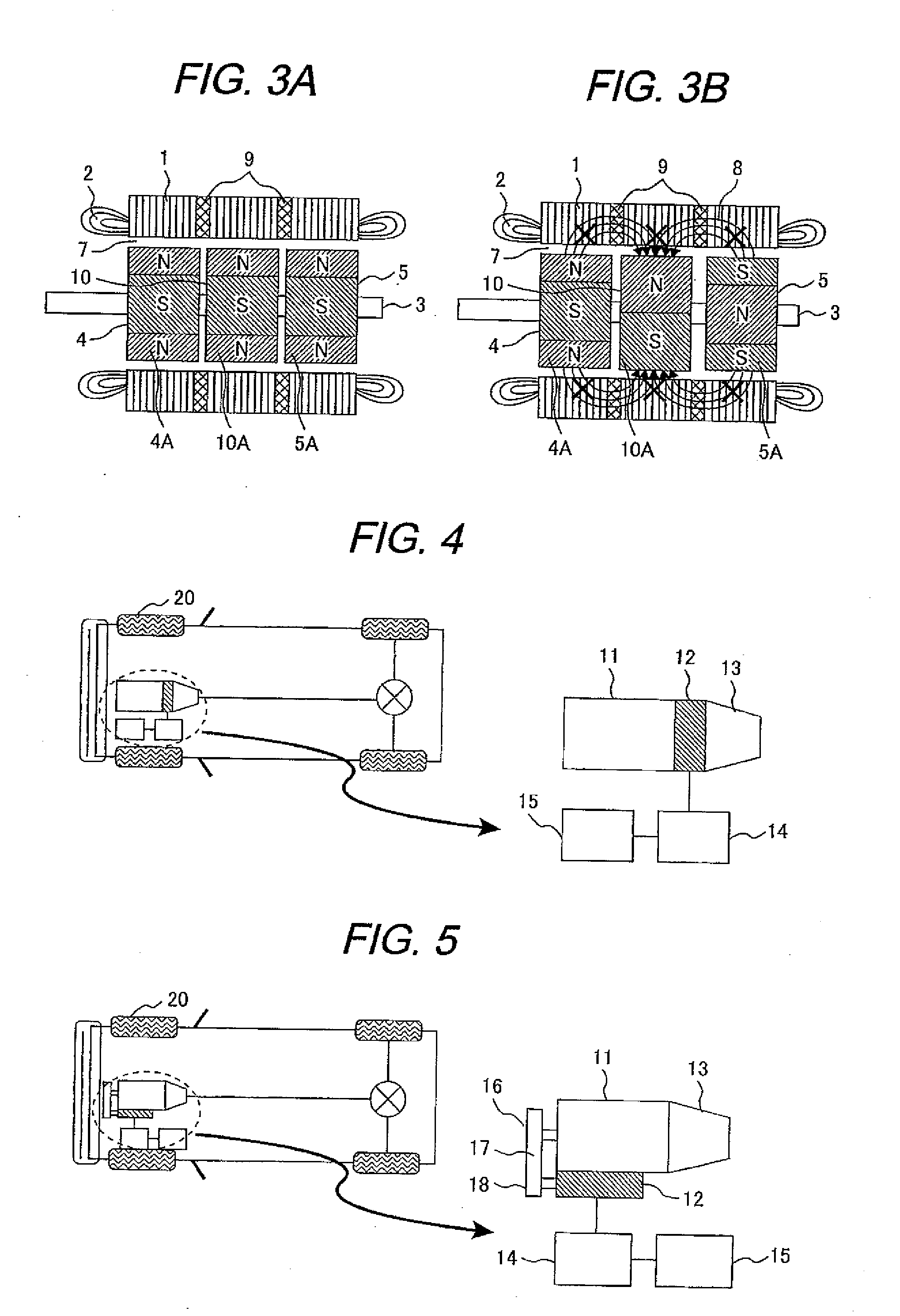
[0035]As shown in FIG. 3, the present embodiment has a structure in which a third rotor 10 is provided between the first rotor 4 and the second rotor 5 and two magnetoresistive layers 9 are provided in the stator core 1 of an electric rotary machine. Namely, the rotor is divided into three in the rotor shaft direction, the stator core is also divided into three in the same direction as the rotor, and the doughnut-shaped magnetoresistive layers are interposed respective between the divided stator cores. Namely, the machine has a structure in which one magnetoresistive layer 9 is provided at a portion in the stator core 1 corresponding to the position ...
embodiment 3
[0042]In the present embodiment, an example will be explained in which the electric rotary machine as proposed in the present invention is applied to a driving system for a hybrid car.
[0043]FIG. 4 shows an arrangement of a driving system for a hybrid car. The driving system for the hybrid car comprises wheels 20, an internal combustion engine (hereafter its called as engine) 11 for driving the wheels, a transmission 13 for controlling velocity of the vehicle, and a permanent magnet type synchronous electric rotary machine (hereafter its called as electric rotary machine 12) and the transmission 13. The electric rotary machine 12 is one having the characteristics as explained in connection with the embodiment 1 or embodiment 2.
[0044]The electric rotary machine 12 is mechanically coupled between the engine 11 and the transmission 13 as described above.
[0045]For the coupling between the engine 11 and the electric rotary machine 12, methods are employed such as a method of directly conn...
PUM
 Abstract
Description
Claims
Application Information
 - R&D
- Intellectual Property
- Life Sciences
- Materials
- Tech Scout
- Unparalleled Data Quality
- Higher Quality Content
- 60% Fewer Hallucinations
Browse by: Latest US Patents, China's latest patents, Technical Efficacy Thesaurus, Application Domain, Technology Topic, Popular Technical Reports.
© 2025 PatSnap. All rights reserved.Legal|Privacy policy|Modern Slavery Act Transparency Statement|Sitemap|About US| Contact US: help@patsnap.com


